Electrical connections, 3 setting the limit switch – KROHNE DK 46 I-DK 47 I EN User Manual
Page 16
4
ELECTRICAL CONNECTIONS
16
DK46I - DK47I
www.krohne.com
08/2008 • 4000360001 MA DK46I-47I-R01-en
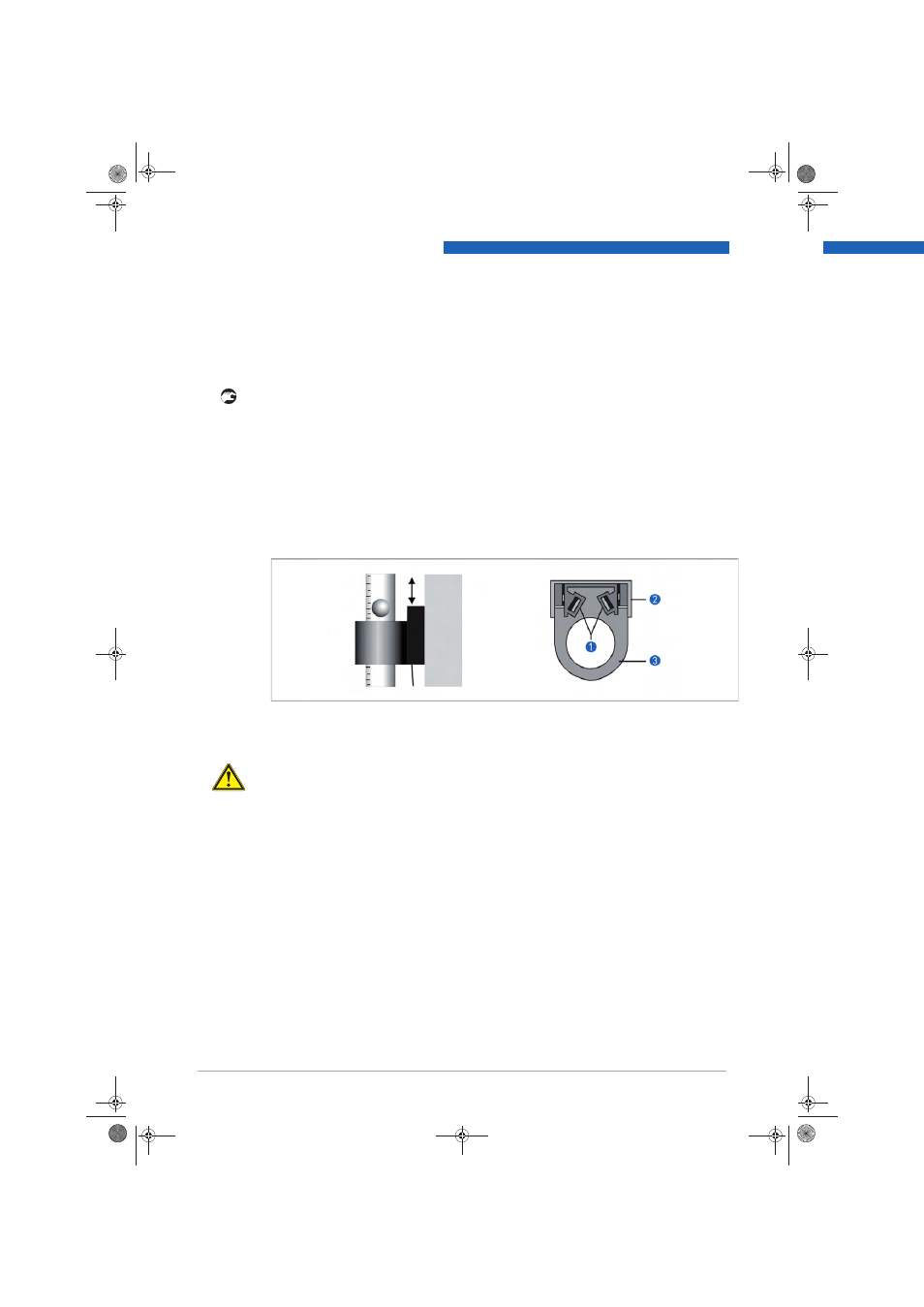
4.3 Setting the limit switch
Following procedure is to perform (DK../../K):
•
Detach clamping screws
1
•
Slide the limit switches over the measuring glass.
•
Use the two clamping screws
1
to fasten the limit switch
3
to the back rail
1
of the
measuring device.
•
Reinstall the protection cover after installation.
To install, first remove the measuring glass as described under chapter Maintenance.
The connecting lead for the limit switch is routed the hole in the device bottom fitting and sealed.
For bistable limit switches with external EMC filter in separate DIN-rail housing, observe the
following:
EMC filter unit and back rail of the flowmeter must be galvanically connected and grounded.
An isolation switching amplifier with intrinsically safe control circuits NAMUR is necessary for
operation of the NAMUR limit switches.
CAUTION!
When setting the ring sensor, make sure the cable is laid such that it cannot be damaged!
Avoid CANT - glass breakage!
MA_DK46I_47I_R01_en_PRT.book Page 16 Tuesday, August 5, 2008 7:03 AM