General, Items included with supply, Software history – KROHNE IFC 090 Converter PROFIBUS User Manual
Page 3: Profibus-pa
Supplementary Documentation IFC 090, IFC 090 i with PROFIBUS-PA
KROHNE Messtechnik GmbH & Co. KG ∑ Ludwig-Krohne-Str. 5 R D-47058 Duisburg
3/7
Tel.: 0203-301 309 R Fax: 0203-301389 ∑ e-mail: [email protected]
Control system (PLC)
Class 1 master
Segment
coupler/link
Analog I/O module
PROFIBUS-PA
4-20 mA
HART device
Power
Supply
PROFIBUS-PA
Segment
coupler/link
PROFIBUS-DP, up to 12 Mbit/s
Engineering or operation
control tool
Class 2 master
, 30) /&
1
2
3
4
5 6
, 30 )/&
1
2
3
4
5
6
1000
900
800
700
600
500
400
300
200
kg/h
100
RP
,30)/&
H250
SN
58 6
67 7/01 -03
M C
H2 50/RR/ M9/K2/ ESK-Z
C
K25.2
1.45 71
F
CI V 2 5 1.4 571
M D
1997
C2H50H
D
0.9 3
kg /l
V
2. 5
mPa.s
T
2 3.5
C
P
0. 4
MPa
FIA 1025
kg
0
3
6
8
7
2
General
These Instructions are supplementary to the ìInstallation and Operating Instructions IFC 090 K / Fì dated 12/96. The
details given there, in particular the Safety Information, are valid and should be observed. These Supplementary
Instructions provide only additional information for device operation and connection to a PROFIBUS-PA fieldbus.
Attention: Please set the controller to manual mode before changing parameters of the IFC 090.
Items included with supply
In addition to the standard scope of supply, these Supplementary Instructions for the IFC 090 with PROFIBUS-PA
interface, plus a diskette with all available GSD files of KROHNE devices.
Software history
Issued
Signal converter
User program
Instructions
month/year Hardware
Firmware
Hard-
ware
Operating
system
Soft-
ware
Device
User
program
09/98
PROFIBUS-
PA Module
1.00
12/96+Supplement
01/99
05/99
PROFIBUS-
PA Module
2.00/990505 PC
Windows 95,
98, NT 4.0
PDM
≥
V 4.1.1
12/96+Supplement
05/99 + 08/99, 03/00
07/00
PROFIBUS-
PA Module
2.00/
PC
Windows 95,
98, NT 4.0
PDM
≥
V 4.1.1
12/96+Supplement
07/00
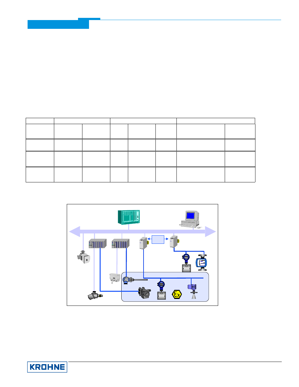
1. PROFIBUS-PA
The above diagram shows a typical instrumentation with PROFIBUS-PA devices in hazardous and non-hazardous
locations, including connection of conventional devices (e.g. with 4-20mA signals) to the PROFIBUS-PA. The
PROFIBUS-PA is normally connected to a segment coupler which, among other things, carries out conversion to the
PROFIBUS-DP. Here, it needs to be noted in particular that the segment coupler is normally set to a fixed baud rate
on the DP side.
Further information on the planning and operation of PROFIBUS-PA networks is to be found in the KROHNE
brochure ìPROFIBUS-PA networksî.