Modbus protocol, 7 input registers – KROHNE GFC 300 Modbus User Manual
Page 12
6
MODBUS PROTOCOL
12
GFC 300
www.krohne.com
03/2012 - 7312402100 - AD Modbus GFC 300 R01 en
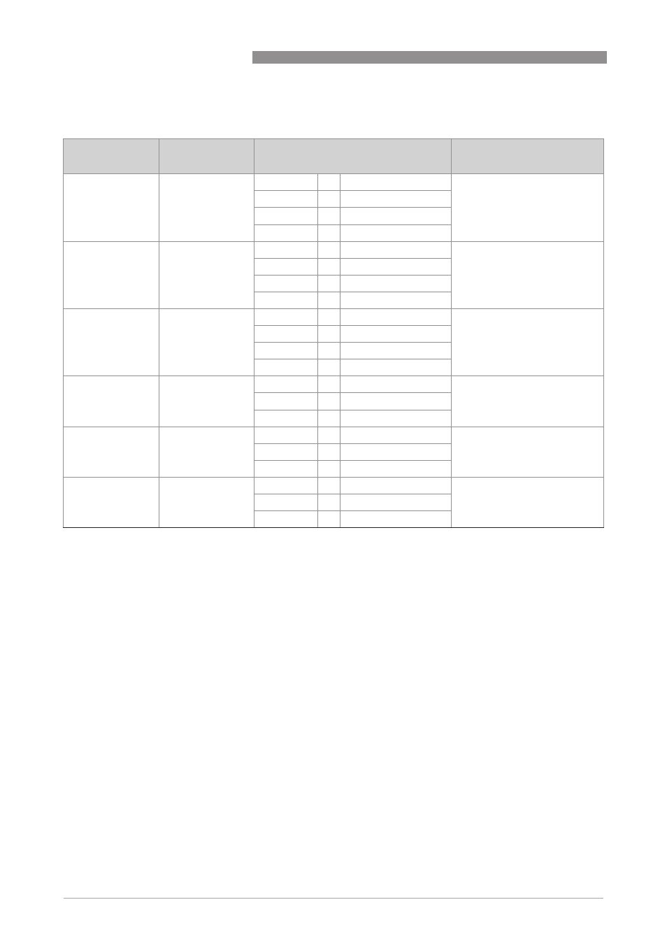
6.6.2 Counter controls
6.6.3 Start calibration functions
No calibration functions have been foreseen in the Modbus Interface.
6.7 Input registers
Measurement and status values are read only and can be accessed as Modbus "Input Registers".
Function code is 04 (0x04).
Input register (3)0018 is not used for the gas option. This address has been included to have the
same layout of the higher addresses of cyclic values.
Modbus protocol
address
Description
Settings
Converter Fct. No.
3000
Start / Stop
Counter 1
Write
1
start counter
C3.1.8 / C3.1.9
Write
0
stop counter
Read
1
counter is running
Read
0
counter is stopped
3001
Start / Stop
Counter 2
Write
1
start counter
C3.2.8 / C3.2.9
Write
0
stop counter
Read
1
counter is running
Read
0
counter is stopped
3002
Start / Stop
Counter 3
1
Write
1
start counter
C3.3.8 / C3.3.9
Write
0
stop counter
Read
1
counter is running
Read
0
counter is stopped
3003
Reset Counter 1
Write
1
reset counter
C3.1.6
Write
0
-
Read
0
-
3004
Reset Counter 2
Write
1
reset counter
C3.2.6
Write
0
-
Read
0
-
3005
Reset Counter 3
1
Write
1
reset counter
C3.3.6
Write
0
-
Read
0
-
1 Only available in converters with IO2. A write attempt to a non-existing counter will cause an error response.