Modbus protocol, 3 addressing, 4 overview of supported functions – KROHNE GFC 300 Modbus User Manual
Page 10
6
MODBUS PROTOCOL
10
GFC 300
www.krohne.com
03/2012 - 7312402100 - AD Modbus GFC 300 R01 en
6.3 Addressing
In the following tables the Modbus protocol addresses / data addresses are listed.
Some systems cannot use addresses above 9999. For these systems there is the possibility to
use the listed addresses but
• for Input Registers omit the leading 3 of 3xxxx;
• for Holding Registers omit the leading 4 of 4xxxx;
• for Input Registers replace the leading 20 of 20xxx by 9xxx.
Sometimes register numbers are asked for. The register numbers
register numbers
register numbers
register numbers can be calculated by adding a
1 to the protocol address and using a prefix according to the block:
• prefix 1 for coils
• prefix 3 for Input Registers
• prefix 4 for Holding Registers
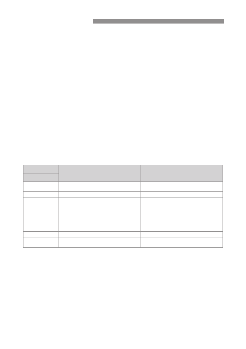
6.4 Overview of supported functions
The following table shows Modbus functions supported by RS485 interface.
Function code
Name
Access to
hex
dec
01
01
Read Coil
Status of calibration functions (not applicable)
Counter status (start/stop)
03
03
Read Holding Register
Acyclic Registers
04
04
Read Input Register
Cyclic Register
05
05
Write Single Coil
Cold start
Warm start
Error reset
Start calibration function (not applicable)
Start / stop counter
08
08
Diagnostics
-
10
16
Write Multiple Register
Acyclic Registers
2B
43
Encapsulated Interface Transport
Transparent Channel
Read Device Identification