KROHNE VARIFLUX IFM 6080 K-EEx-i-EEx EN User Manual
Page 21
ALTOFLUX IFM x080 K-EEx and ALTOFLUX IFM x080 K / i-EEx
21
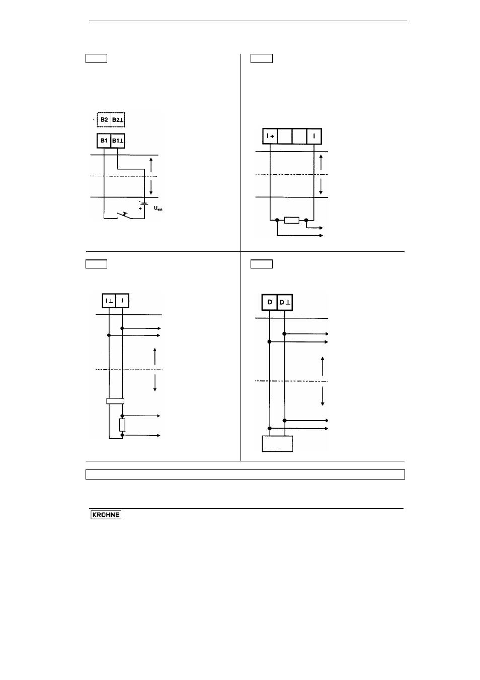
Connection diagrams 9 to 12 of the intrinsically safe signal in-/outputs
9
Control input C
passive
10
HART
active
Versions:
Ex-i1, Ex-i4, Ex-i6, Ex-i8
Version: Ex-i3
U
ext
= 7 - 30 V DC
I
max
≤ 110 mA
Connection to terminals B1/B1
⊥ and/or B2/B2⊥
IFC 090 i-EEx
IFC 090 i-EEx
hazardous area
hazardous area
safe area or
safe area or
hazardous area (
*
)
hazardous area (
*
)
to
HART
communicator
or SMART converter
11 HART
passive
12 Fieldbus
Versions:
Ex-i1, Ex-i2, Ex-i7
Versions:
Ex-i2, Ex-i4, Ex-i7, Ex-i8
IFC 090 i-EEx
IFC 090 i-EEx
to next HART device
to next Fieldbus
device
or bus terminator
hazardous area
hazardous area
safe area or
hazardous area (
*
)
safe area or
hazardous area (
*
)
Bus supply device
to HART
to Bus master
communicator
or SMART converter
Bus supply device
(
*
) Important note:
Only if the measuring devices are also explosion protected !