KROHNE VARIFLUX IFM 6080 K-EEx-i-EEx EN User Manual
Page 20
ALTOFLUX IFM x080 K-EEx and ALTOFLUX IFM x080 K / i-EEx
20
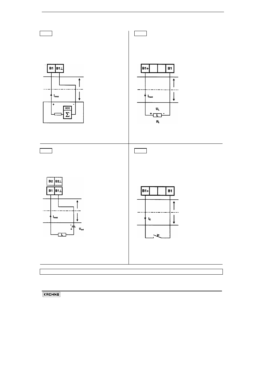
Connection diagrams 5 to 8 of the intrinsically safe signal in-/outputs
5
Pulse output P
passive
6
Status output S
active
Versions:
Ex-i1, Ex-i4, Ex-i6, Ex-i8
Version: Ex-i5
U
ext
= 6 - 30 V
U
int
= 20 V DC
I
max
≤ 110 mA
R
int
= 260
Ω
for active EC
U
L
= 20×R
L
/ (260+R
L
)
IFC 090 i-EEx
IFC 090 i-EEx
hazardous area
hazardous area
safe area or
safe area or
hazardous area (
*
)
hazardous area (
*
)
active counter
7
Status output S
passive
8
Control
input
C
active
Versions:
Ex-i1, Ex-i4, Ex-i6, Ex-i8
Version: Ex-i5
U
ext
= 6 - 30 V
U
int
= 20 V DC
I
max
≤ 110 mA
I
contact
≤ 6 mA
Connection to terminals B1/B1
⊥ and/or B2/B2⊥
IFC 090 i-EEx
IFC 090 i-EEx
hazardous area
hazardous area
safe area or
safe area or
hazardous area (
*
)
hazardous area (
*
)
(
*
) Important note:
Only if the measuring devices are also explosion protected !