3 replacement of power fuse(s) – KROHNE ALTOSONIC V EEx EN User Manual
Page 14
ALTOSONIC V
10
1. Unscrew all bolts of the flameproof box and open the cover.
2. Disconnect the SMB connectors of the coaxial cables, the 3-pole power supply connector
and 5-pole connector of the in-/output circuits at the electronics unit(s) involved.
3. Unscrew the two screws A of the display unit and turn display unit carefully aside or
remove the unit completely by taking out the flat cable connector.
4. Unscrew the two mounting screws B of the electronics unit and screw C, which fixes the
copper earth strip at the back of the housing. Remove the unit(s) from the box.
5. Check the new electronics unit if the voltage setting (only applicable for AC supplies) and
power fuse rating are correct. Change the voltage setting or exchange the fuse if
necessary.
6. Install the electronics unit into the box and plug the 3-pole and 5-pole connectors back in.
Fixate screws B and C and screw the display unit back on via screws A, after the flat
cable connector is connected. Plug the numbered SMB connectors to the corresponding
numbered SMB receptacles on the electronics unit.
7. Close the cover of the flameproof box and screw all bolts tightly with the right size socket-
head screw wrench.
Note the "After opening" instructions during reassembling.
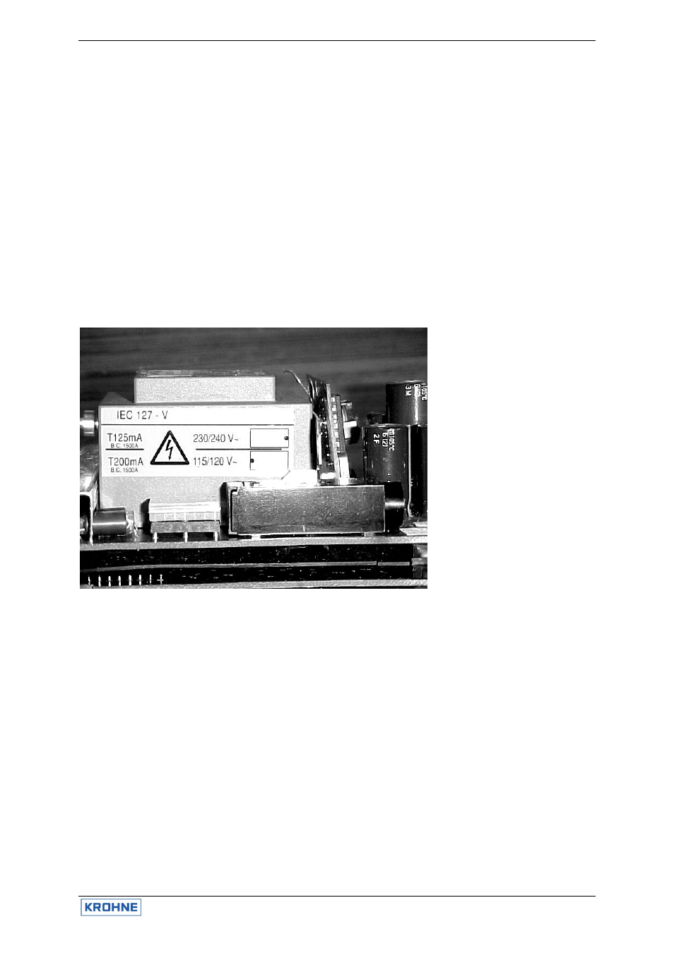
1. Mains transformer
115/230 VAC version
2. Sticker with fuse rating
3. Indication of voltage
selector (black dot =
notch)
4. Mains fuse F1 (in fuse-
holder)
5. Voltage selector
6. Side of display unit
Figure 4: Power supply version 115/230 V AC
3.3 Replacement of power fuse(s)
3.3.1 AC versions 115/230 V AC and 100/200 V AC
Before commencing work, note the "Before opening" instructions, then continue as follows:
1. Unscrew the bolts and open the cover of the flameproof box.
2. Unscrew the two screws A of the display unit and turn the display unit carefully aside.
3. The fuse-holder, in which the power fuse in accordance with IEC 127-2 size Ø5 x 20 mm
is mounted, is now accessible to replace the defect power fuse F1 by a new fuse with the
same rating. The fuse rating depends on the voltage setting of the power supply unit
(T200mA for 100/115V AC and T125mA for 200/230 V AC). See also the yellow sticker
that is glued on the mains transformer as shown in the figure on the previous page.
4. Reassemble the unit in reverse order (points 2 and 1).
Note the "After opening" instructions during reassembling.
1
3
2
4
5
6