Hazardous locations of zone 1 and 2, 3 connection diagram, Altosonic v 7 – KROHNE ALTOSONIC V EEx EN User Manual
Page 11: Ufc-v/…-eex ultrasonic flow converter, Beam flow tube, Ufs 500 f/5str/…-eex primary head
ALTOSONIC V
7
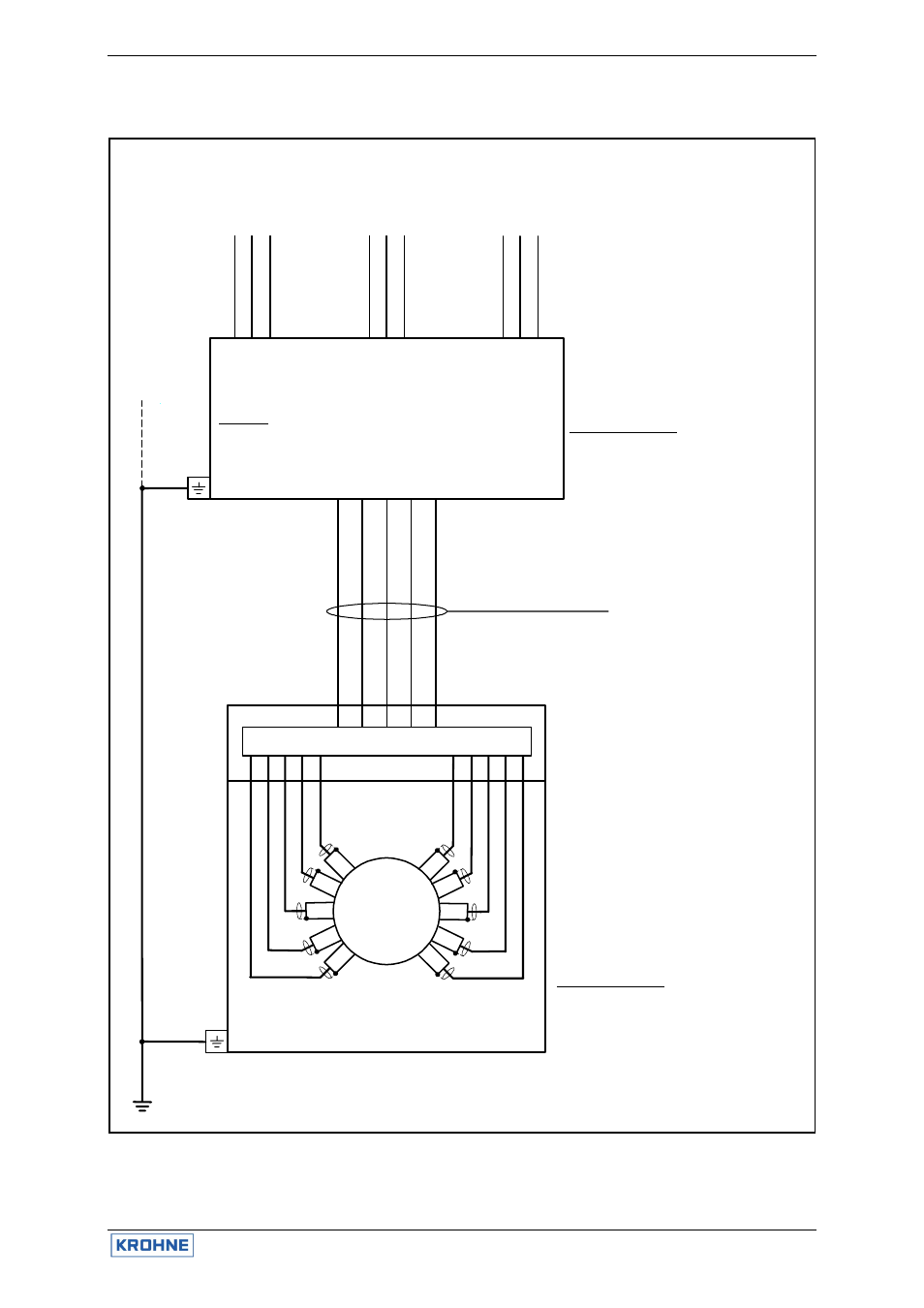
2.3 Connection
diagram
Hazardous locations
of Zone 1 and 2
E
Q
UI
P
O
T
E
NT
IA
L B
O
N
D
IN
G
CO
NDU
C
T
O
R
≥
2.
5 m
m
2
(A
W
G
1
2)
5x MR04 connecting cables
Entity parameters:
V
o
= 8.72 V
I
o
= 380 mA
C
o
= 1.2 µF
L
o
= 0.17 mH
RS485 data
communication
UFC-V/…-EEx Ultrasonic Flow Converter
Standard version (-20°C
≤ T
a
≤ +60°C):
Flameproof box type CCFE 45 (CESI 00 ATEX 036 U)
with 5x UFC 500…-EEx electronics units
Optional: 1x heating element (
≤ 30 W) + 1x thermostat T1
or
Low-temperature version (-55/-50°C
≤ T
a
≤ 60°C):
Flameproof box type CXJ12188-CEN-… + 5x UFC 500…-EEx
+ 1x heating element (
≤ 200 W) + 2x thermostats T1 and T2
L N PE
1 2
⊥
L N PE
Power supply heater
110-240Vac/dc; 50/60Hz
@ max. 200W or
24Vdc @ max. 30 W.
Power supply UFC 500's
24-240Vac; 50/60Hz or
24Vdc
Power: 5x12 VA or 5x8W
Junction box
5-beam
flow tube
S1
S5
S9
S7
S3
S2
S6
S10
S8
S4
UFS 500 F/5STR/…-EEx
Primary Head
Intrinsically safe sensor circuits
10x SMB connections for intrinsically safe sensor circuits
Entity parameters:
V
max
= 13.1 V
I
max
= 600 mA
C
i
=
3.9
nF
L
i
= 38.3 µH