INOR LCD-H20 User Manual
Page 2
LIMITED WARRANTY
INOR Process AB, or any other affiliated company within the Inor Group (hereinafter jointly referred to as
”Inor”), hereby warrants that the Product will be free from defects in materials or workmanship for a period
of five (5) years from the date of delivery (”Limited Warranty”). This Limited Warranty is limited to repair
or replacement at Inor’s option and is effective only for the first end-user of the Product. Upon receipt of
a warranty claim, Inor shall respond within a reasonable time period as to its decision concerning:
1 Whether Inor acknowledges its responsibility for any asserted defect in
materials or workmanship; and, if so,
2 the appropriate cause of action to be taken (i.e. whether a defective
product should be replaced or repaired by Inor).
This Limited Warranty applies only if the Product:
1 is installed according to the instructions furnished by Inor;
2 is connected to a proper power supply;
3 is not misused or abused; and
4 there is no evidence of tampering, mishandling, neglect, accidental damage, modification
or repair without the approval of Inor or damage done to the Product by anyone other
than Inor.
This Limited Warranty is provided by Inor and contains the only express warranty provided.
INOR SPECIFICALLY DISCLAIMS ANY EXPRESS WARRANTY NOT PROVIDED HEREIN AND
ANY IMPLIED WARRANTY, GUARANTEE OR REPRESENTATION AS TO SUITABILITY FOR
ANY PARTICULAR PURPOSE, PERFORMANCE, QUALITY AND ABSENCE OF ANY HIDDEN
DEFECTS, AND ANY REMEDY FOR BREACH OF CONTRACT, WHICH BUT FOR THIS PRO-
VISION, MIGHT ARISE BY IMPLICATION, OPERATION OF LAW, CUSTOM OF TRADE OR
COURSE OF DEALING, INCLUDING IMPLIED WARRANTIES OF MERCHANTABILITY AND
FITNESS FOR A PARTICULAR PURPOSE. EXCEPT AS PROVIDED HEREIN, INOR FURTHER
DISCLAIMS ANY RESPONSIBILITY FOR LOSSES, EXPENSES, INCONVENIENCES, SPECIAL,
DIRECT, SECONDARY OR CONSEQUENTIAL DAMAGES ARISING FROM OWNERSHIP OR
USE OF THE PRODUCT.
Products that are covered by the Limited Warranty will either be repaired or replaced at the option of
Inor. Customer pays freight to Inor, and Inor will pay the return freight by post or other “normal” way of
transport. If any other type of return freight is requested, customer pays the whole return cost.
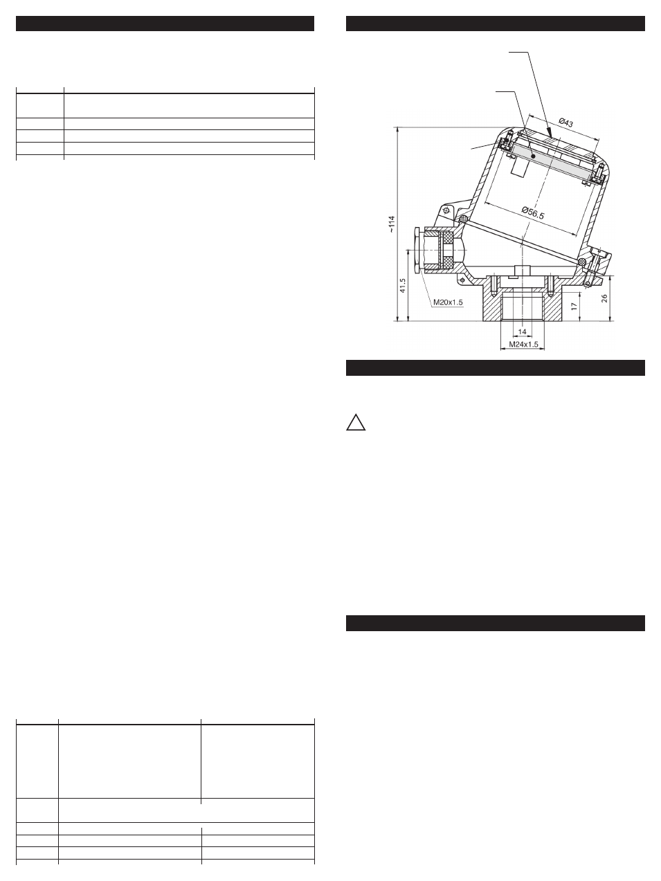
MOUNTING/DIMENSIONS CONNECTION HEAD
Programming: The programming is executed through 3 keys
mounted on the bottom of the display. The central key is the Enter
(F) key. The lateral keys act as the up
and down
digit; they
also act as selec tion of the parameters.
!
CONFIGURATION
Key
Function
F
Access to the programming; move to the following parameter menu;
saving of data and close of the programming
Decreasing digit; selection/set-up of a parameter
Increasing digit; selection/set-up of a parameter
+
“Escape”
Operation: Press the key F for more than 3 seconds to get access to the
programming procedure. The dis play will visualize the “dP” function, which
is the first programming section: Decimal Point. By pressing the
(increase)
and (decrease) keys it’s possible to scroll all the other programming win-
dows. At the end of the programming phase the modified parameters are
stored automatically and retained also during the switch off of the instru-
ment.
Programming procedure:
Set-up of the decimal point (dP)
Press the or
keys to select the decimal point position (from zero to 3
decimals). Press F to confirm. Default = 1 decimal
Set-up of the engineering value related to the zero point (ZErO)
Press the or keys to select the engineering value zero (-1999 to
9999). Press F to confirm. Default = 0.0
Set-up of the engineering value related to the span range (SPAn) Press
the or keys to select the engineering range value (-1999 +9999).
Press F to confirm. Default = 100.0
Set-up of the limit on the input current (Li) This parameter allows to
select the over-load limit of the visualization.
If Li = 0, when the current overcomes the 20 mA value, the display will indicate
the OverLoad mes sage OL (-OL when the current is lower that 4 mA).
If Li = 1, the visualization will be extended of a 10% over the 4...20 mA
range, before indicating the overload. In both cases, overcoming the display
maximum readings (-1999 +9999), the over load message will be indicated.
Default = 1
Set-up of the filter (FiLt) When the 4...20 mA is disturbed it is possible
to select an higher value of FiLt in order to get a more stable and clear
visualization on the display.
Press the key to increase the filter value on the input and the key to
decrease the filter value.
It’s possible to set-up different values from 1 to 8; when FiLt = 1 no filter is
applied on the input and the digital reading occurs every 250 ms.
In this case the updating period of the display will be 250 ms multiplied by
the FiLt value. Example: if FiLt = 5 the updating period of the display will be
1.25 s. Default = 2
Set-up of resolution (riS) This function allows to set-up the resolution
of the display; when riS = 1 the display will indicate all the available digit in
the scale, within the programmed range.
When riS = 2 the steps between two consecutive readings will be doubled:
with riS = 2 it will not be possible to indicate odd numbers.
Selectable values for riS are: 1, 2, 5 and 10.
It is suggested to increase the resolution only if the set range is very large
(example 10000 points) and/or if the 4...20 mA signal is quite unstable: on
the contrary the maximum resolution is normally used. Default = 1
Summary
Key
Function
Disply
SCROLL
Set-up of the decimal point
DP / 000.0
or
Set-up of the engineering value ZERO ZErO / 0.0
Set-up of the engineering range SPAN SPAn / 100.0
Set-up of the OverLoad Limit
Li / 0
Set-up of the input Filter
FiLT / 1
Set-up of the Resolution
riS / 1
F
Access to enter the programming window. Allow to exit the
programmimg window and to save the modifications.
Increasing digit
0 to 9
Decreasing digit
9 to 0
+
Exit the programmimg without saving
CALIBRATION
By pressing contemporary the
+
keys for more than 3 s, it is possible
to access to the cal ibrating function where it is possible to calibrate the zero
and the full scale of the A/D converter of the digital indicator.
Entering this procedure and modifying the parameters will change
the factory cal ibration data. This function must be executed by spe-
cialised personnel only by using adequate instrumentation. A wrong calibra-
tion will affect the right functionality of the instru ment itself.
Step 1: Zero-point calibration
Inside the calibration window, select the ZERO point calibration (C4) by
pressing
or
keys. Apply a 4 mA current to the instrument, wait for the
stabilization of the signal and of the indication and press the key F until the
indication CAL will appear on the display. After few seconds, the new engi-
neering ZERO value will be indicated.
Exit the Zero-point calibration by pressing
+
keys together and proceed
with the Full Scale calibration.
Step 2: Full scale calibration
Inside the calibration window, select the Full Scale calibration (C20) by
pressing
or
keys. Apply a 20 mA current to the instrument and pro-
ceed as for the Zero-point calibration.
Window
(polycarbonate)
LCD-H20
Mounting kit
KDST1