INOR ICON GB User Manual
Page 2
CONTENTS
USB INTERFACE DIMENSIONS
1.
2.
4.
5.
6.
3.
CONFIGURATION
ORDERING INFORMATION
LIMITED WARRANTY
INOR Process AB, or any other affiliated company within the Inor Group (hereinafter
jointly referred to as ”Inor”), hereby warrants that the Product will be free from defects
in materials or workmanship for a period of five (5) years from the date of delivery
(”Limited Warranty”). This Limited Warranty is limited to repair or replacement at
Inor’s option and is effective only for the first end-user of the Product. Upon receipt
of a warranty claim, Inor shall respond within a reasonable time period as to its
decision concerning:
1 Whether Inor acknowledges its responsibility for any asserted defect in
materials or workmanship; and, if so,
2 the appropriate cause of action to be taken (i.e. whether a defective
product should be replaced or repaired by Inor).
This Limited Warranty applies only if the Product:
1 is installed according to the instructions furnished by Inor;
2 is connected to a proper power supply;
3 is not misused or abused; and
4 there is no evidence of tampering, mishandling, neglect, accidenta damage,
modification or repair without the approval of Inor or damage done to
the Product by anyone other than Inor.
This Limited Warranty is provided by Inor and contains the only express war-
ranty provided.
INOR SPECIFICALLY DISCLAIMS ANY EXPRESS WARRANTY NOT
PROVIDED HEREIN AND ANY IMPLIED WARRANTY, GUARANTEE
OR REPRESENTATION AS TO SUITABILITY FOR ANY PARTICULAR
PURPOSE, PERFORMANCE, QUALITY AND ABSENCE OF ANY HIDDEN
DEFECTS, AND ANY REMEDY FOR BREACH OF CONTRACT, WHICH BUT
FOR THIS PROVISION, MIGHT ARISE BY IMPLICATION, OPERATION
OF LAW, CUSTOM OF TRADE OR COURSE OF DEALING, INCLUDING
IMPLIED WARRANTIES OF MER-CHANTABILITY AND FITNESS
FOR A PARTICULAR PURPOSE. EXCEPT AS PROVIDED HEREIN,
INOR FURTHER DISCLAIMS ANY RESPONSIBILITY FOR LOSSES,
EXPENSES, INCONVENIENCES, SPECIAL, DIRECT, SECONDARY OR
CONSEQUENTIAL DAMAGES ARISING FROM OWNERSHIP OR USE
OF THE PRODUCT.
Products that are covered by the Limited Warranty will either be repaired or replaced
at the option of Inor. Customer pays freight to Inor, and Inor will pay the return
freight by post or other “normal” way of transport. If any other type of return freight
is requested, customer pays the whole return cost.
Item
Part No.
ICON Configuration Kit
70CFGUS001
mm/inches
The USB Interface is powered from the PC´s USB port.
There are three LED indicators on the USB Interface: “USB”, “PC” and “DEV”.
They are indicators to make the understanding of the communication between
PC and transmitter easier. Their functions are described below:
• “USB” LED indicates data transfer. It lights during data transfer, other-
wise it is off.
• “PC” LED indicates connection between Configuration program and PC.
When configuration is made from IPRO, MinIPAQ Soft or ProfiSoft, it is
green when the configuration program is open. With all other configura-
tion programs it is green only during reading or writing to transmitter.
• “DEV” LED indicates the transmitter connection status.
If it’s green, the connected transmitter is detected by the USB Inter-
face. Flashing green indicates that the USB Interface is waiting for a
new transmitter from the same product family, e.g. changing to a new
device. When it´s red no transmitter is detected by the USB Interface
and any sort of transmitter can be connected to the USB Interface.
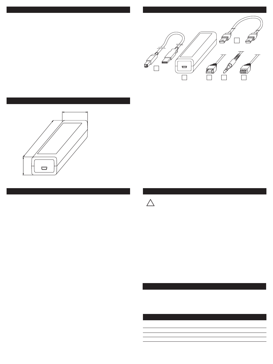
DESCRIPTION USB INTERFACE
1. USB communication cable (connection between PC and USB Interface).
2. USB Interface
3. Mini USB to Mini USB adapter (USB Interface to Transmitter)
4. Mini USB to four pole rectangular connector (USB Interface to
transmitter)
5. Mini USB to 3,5 mm tele plug connector (USB Interface to transmitter)
6. Mini USB to three pole rectangular connector (USB Interface to
transmitter)
For transmitter configuration using the ICON Configuration Kit, see User
instructions for the specific transmitter.
36/1.42
114/4
.49
26/1.02
TRANSMITTER COMMUNICATION
The following transmitters have to be connected to a
power supply before communication: IPAQ-H, IPAQ-L,
IPAQ-4L, ProfIPAQ-H and ProfIPAQ-L
1. After installing the drivers for the USB interface and configuration soft-
ware, connect the USB cable and the USB interface to a free USB port
of your PC.
2. Connect the transmitter to the USB interface with a suitable Mini USB
cable.
3. Start up the ConSoft program.
4. Click on the upper left “Read from transmitter” button. ConSoft will
connect to the transmitter and open a relevant window for transmitter
configuration.
5. A new transmitter can at any time be connected, without restarting
ConSoft, by clicking on “Read from transmitter”.
!