Measurements, Caution – HT instruments QUICKLAN6055 User Manual
Page 7
QUICKLAN 6055
EN - 6
5. MEASUREMENTS
5.1. CABLING
TEST
VERIFY
The wire mapping of RJ45 LAN cables is tested in accordance with its defined cabling
layout. To test a cable perform the below operation:
1. Select the type of cable UTP or STP under test (see § 4.1.3).
2. Connect the cable under test to the meter (see Fig. 1 – part 1) and to the remote unit
by using if necessary through supplied patch cables
3. Press GO key to perform all tests related to the selected type of cable
The remote unit must be necessarily connected otherwise no measurement is
performed
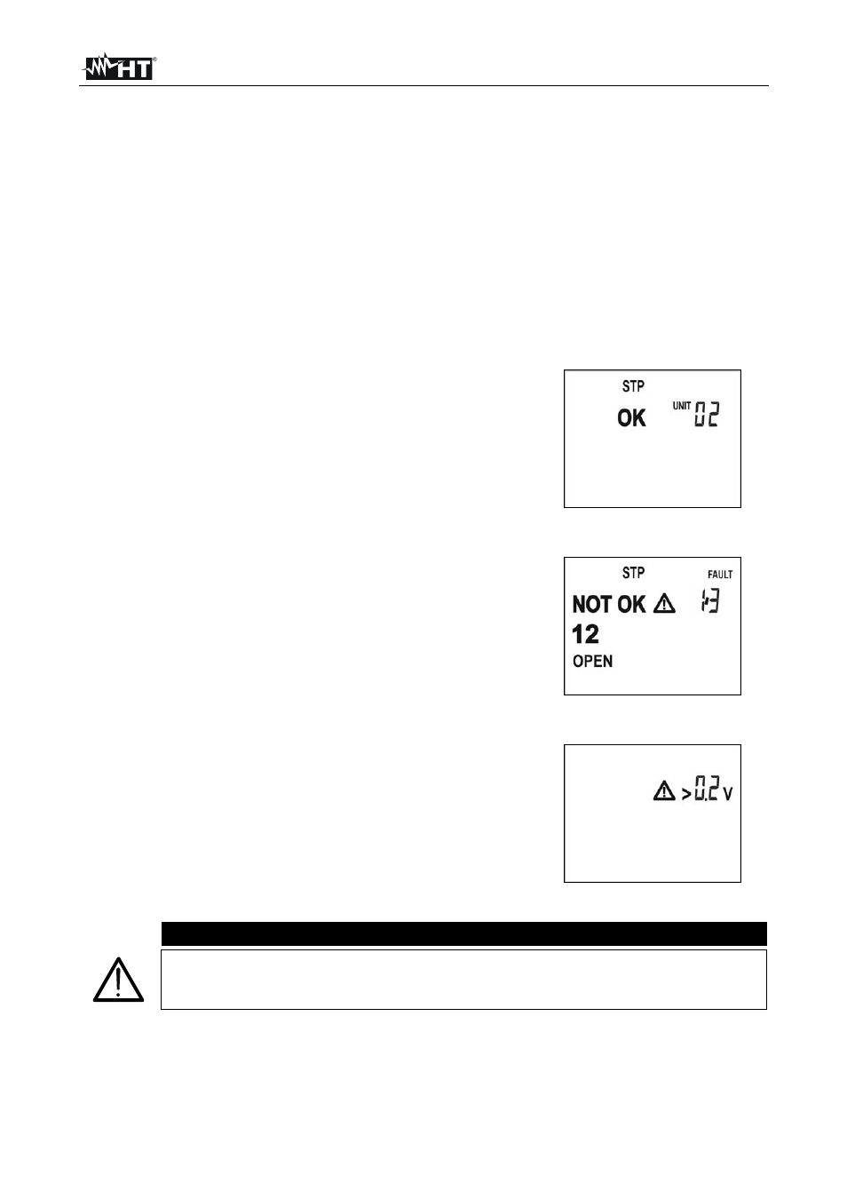
If cabling is correct, a screen like this is displayed (OK).
The identification number refers to the remote identifier
connected to the other end of the cable being tested.
If cabling is not correct, a screen like this is displayed.
Referring to this example:
“NOT OK” indication and caution symbol means that
the test have given some errors
“FAULT 1/3” means that the detected errors are 3, of
which the first one is currently displayed. By pressing
arrow keys it’s possible to run over the remaining
screens and display other cabling errors
Details on the detected error are given on the left
side: the couple 1-2 is OPEN
If the instrument detects the presence of a voltage >
0.2V on the RJ45 input, it shows the message in the
screen on the right and do not perform the test.
Eliminate the cause of the presence of voltage (e.g.:
coupling due to the presence of electrical cables close
to cable of LAN networks)
CAUTION
It’s indispensable to select the right type of cable. If UTP is selected although
a STP cable is tested, test results may be not reliable due to the shield
affecting the measurement.