HT instruments M70 User Manual
Page 10
M70
EN - 9
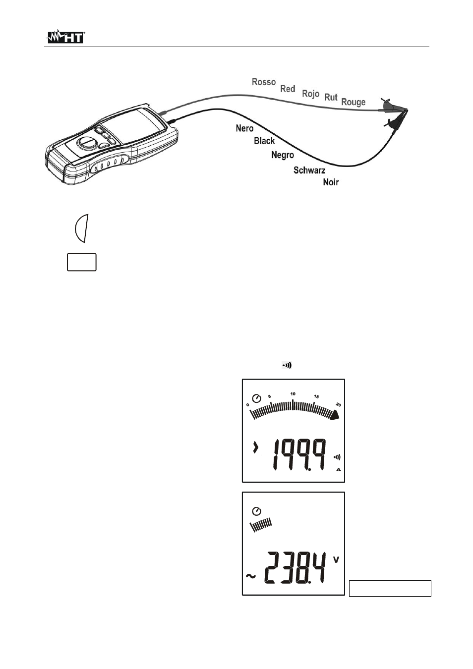
2. Short-circuit the cable ends with each other as shown in Fig. 5 making sure that the
metallic parts of test probes and crocodiles are in good touch
Fig. 5: Connection of the instrument’s terminals during calibration procedure
3.
GO
Press GO to perform the measurement
4.
MODE
PEAK
Press and hold ZERO key for 2s. The instrument resets the resistance of the
cables, the symbol ZERO is displayed
5. The measured value is stored by the instrument and used as offset (which means it’s
deducted from all continuity tests performed) until a new pressing of the ZERO key for
2s that voids the calibration
6. Each time the instrument is switched off or changing position of selector, the
calibrated value is lost
4.4.2. Anomalous
cases
which may occur during
measurement
1. The full scale of the instrument is
199.9
. If the resistance value is higher
than this value, or in case of open or
interrupted probes, the instrument
displays the screen beside.
2. If the voltage present at the terminals is
higher than 24V the instrument does not
perform the test. The screen beside is
displayed
Input voltage