Warning – HT instruments HT4012 User Manual
Page 39
HT4012
EN - 14
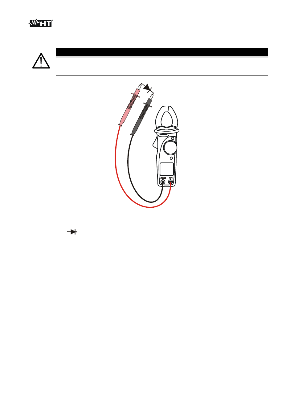
4.3.6. Diode
test
WARNING
Before taking any in circuit resistance measurement, remove power from
the circuit being tested and discharge all the capacitors.
Fig. 9: Use of clamp for diode test
1. Select the “
”
function.
2. Insert the test leads into the jack, the red plug into V/
Ω jack, and black plug into COM
jack, like showed in Fig. 9.
3. Insert the red lead on the anode of diode and black lead on the cathode ones.
4. The correspondent threshold voltage of P-N junction is showed on display.
See also other documents in the category HT instruments Tools:
- COMBI419 (88 pages)
- COMBIG3 (108 pages)
- EQUITEST5071 (44 pages)
- FULLTEST3 (92 pages)
- GEO416 (116 pages)
- HT12 (4 pages)
- HT14N (12 pages)
- HT154 (13 pages)
- HT155 (68 pages)
- HT20 (5 pages)
- HT20 (6 pages)
- HT204 (8 pages)
- HT2055 (35 pages)
- HT21 (17 pages)
- HT210 (19 pages)
- HT2234N (14 pages)
- HT300 (9 pages)
- HT307 (11 pages)
- HT309 (13 pages)
- HT32 (23 pages)
- HT321 (16 pages)
- HT326 (21 pages)
- HT327 (21 pages)
- HT3301 (16 pages)
- HT3320 (30 pages)
- HT37 (24 pages)
- HT4000 (15 pages)
- HT401 (24 pages)
- HT4010 (76 pages)
- HT4011 (21 pages)
- HT4014 (23 pages)
- HT4020 (152 pages)
- HT5 (12 pages)
- HT5000 (31 pages)
- HT6 (16 pages)
- HT603 (5 pages)
- HT70 (6 pages)
- HT701 (26 pages)
- HT7052 (120 pages)
- HT712 (17 pages)
- HT77N (14 pages)
- HT78 (16 pages)
- HT8000 (16 pages)
- HT8051 (74 pages)