Caution – HT instruments HT4011 User Manual
Page 14
HT4011
EN – 13
4.3.6. Continuity test and diode test
CAUTION
Before attempting any resistance measurement, remove power from the
circuit under test and discharge all capacitors, if present.
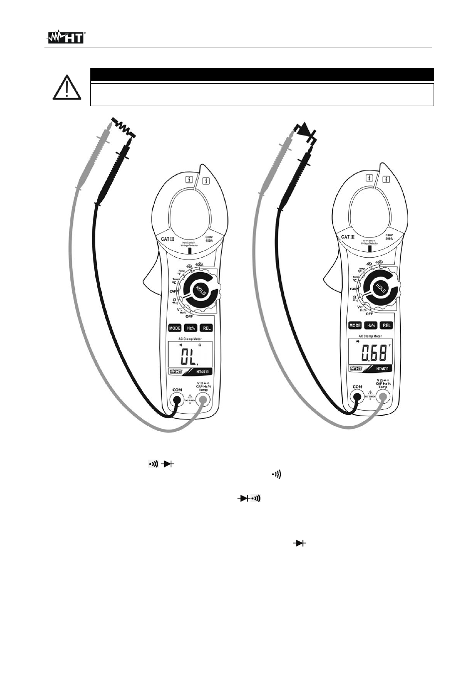
Fig. 7: Use of the clamp for continuity test and diode test
1. Select the position
2. Press the MODE key cyclically until the symbol “
“ is displayed to activate continuity
test.
3. Insert the red cable into input terminal V
CAPHz%Temp and the black cable into
input terminal COM and carry out the continuity test of the object to be measured (see
Fig. 7– left side). An buzzer sounds when the measured value of resistance is lower
than 30
4. Press the MODE key to select diode test. The symbol “
“ appears on the display.
5. Connect the red lead to the anode of the diode and the black lead to the cathode in
case direct polarization measurement is carried out (see Fig. 7 – right side). Invert the
position of the leads in case reverse polarization measurement is carried out.
6. Values on the display between 0.4V and 0.7V (direct) and “OL” (reverse) indicate
correct connection. A value “0mV” indicates that the device is short-circuited, while
“OL” in both directions indicated an interrupted device.