0 wiring diagram da-1 – Detcon DA-1 User Manual
Page 5
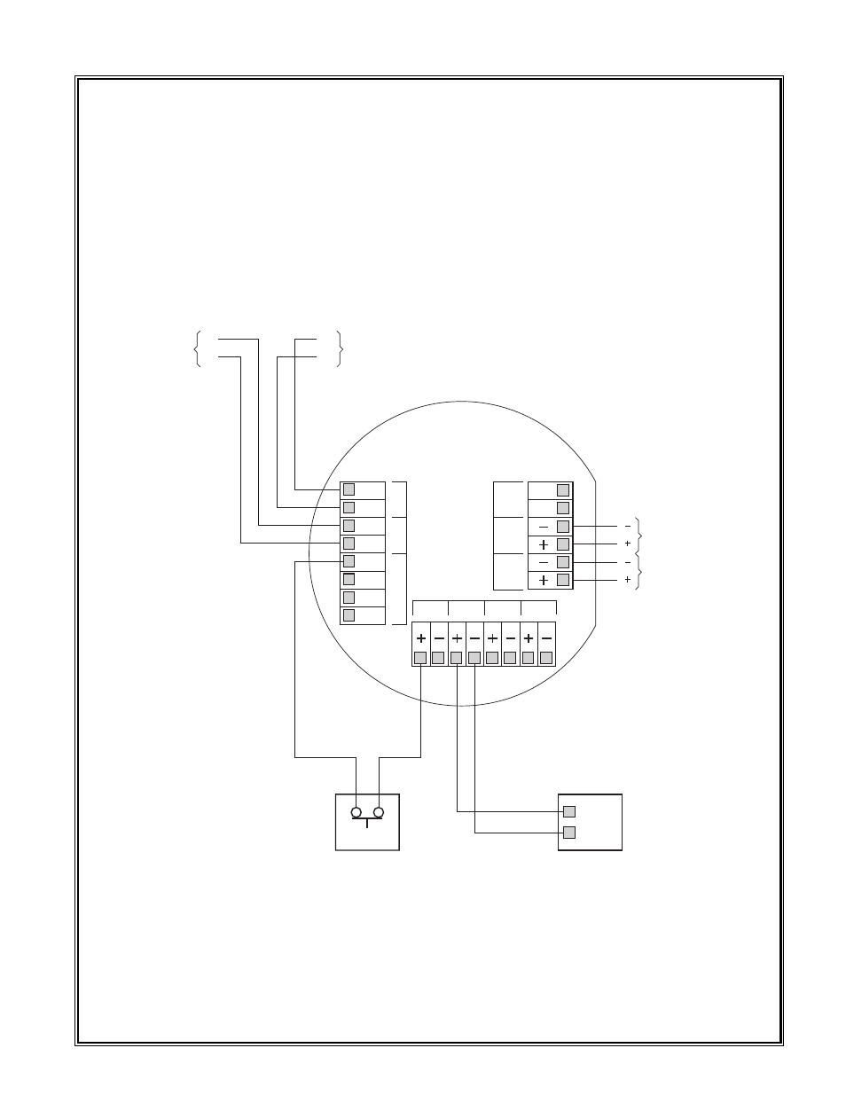
7.0 Wiring Diagram DA-1
All unused inputs should have a single wire connected from one of the digital source terminals to the + input
of that channel, with no signal developing resistor.
Always remove power before plugging or unplugging the device. Damage can occur to the unit if it is pow-
ered during servicing or replacement.
Detcon Model DA-1 PG.5
24VDC to
next device
Fault
Power
Out
Power
In
COM
NO/NC
24VDC from
previous device
A
B
A
B
1
2
3
4
RS-485
Digital Source
RS-485
RS-485 to
next device
A
B
A
B
RS-485 from
previous device
CH1
CH2
CH3
CH4
NC
Emergency Pull Station
Typical
Digital
Input
Typical
4-20mA Analog
Input
+ mA
– mA
Flame Detector
See also other documents in the category Detcon Equipment:
- 12B (16 pages)
- FL-10 (7 pages)
- 10C Facilities (18 pages)
- 10C (29 pages)
- 10B (10 pages)
- 1212-N4X (9 pages)
- 812-N4X (9 pages)
- 1212B (5 pages)
- 612B (5 pages)
- 1610-N4X (28 pages)
- 1010-N4X (14 pages)
- 610-N4X (12 pages)
- 1610-N1 (4 pages)
- 810-N1-24VDC (10 pages)
- 410-N1-24VDC (4 pages)
- MCX-32-N1P (55 pages)
- RD-64X-N4X (41 pages)
- 880RA-N4X (36 pages)
- 880RA-N4X (23 pages)
- 880A-N1R (45 pages)
- 880A-N4X (50 pages)
- 880A-N4X (43 pages)
- X40-08-N4X (70 pages)
- 240 (33 pages)
- SW-AV1-N4 (12 pages)
- SW-AV2-DV1 (12 pages)
- A1V1 (9 pages)
- RXT-300 (47 pages)
- RXT-320 (31 pages)
- CXT-N4X (28 pages)
- SW-HMI-32-N4X (24 pages)
- SW-V1-DV2 (11 pages)
- SW-AV1-DV1 (14 pages)
- SW-AV2-DV2 (12 pages)
- SW-AV1-DV2 (12 pages)
- SmartWireless CX (33 pages)
- SmartWireless CXT (49 pages)
- CX-IR (38 pages)
- CX-DM (44 pages)
- CXT-IR (48 pages)
- CXT-DM (56 pages)
- P-1000 (28 pages)
- 1000 (32 pages)
- 1000_CO2 (32 pages)
- 1000_H2S (34 pages)