11 4 r r, 11 5 ii, Figure 4 - dimensions/mounting detail – Detcon 610A-FB User Manual
Page 6
1
1..4
4 R
R
E
EM
MO
OT
TE
E
R
R
E
ES
SE
ET
T
A remote mounted normally open momentary switch may be used to reset all Model 10A controllers. The
reset function is effective when the Model 10A's respective alarms have been programmed in the latching
position and alarm conditions have passed. Each Model 10A controller has its own alarm reset switch which
is discussed further in section 2.0.
1
1..5
5 II
N
NS
ST
TA
AL
LL
LA
AT
TIIO
ON
N
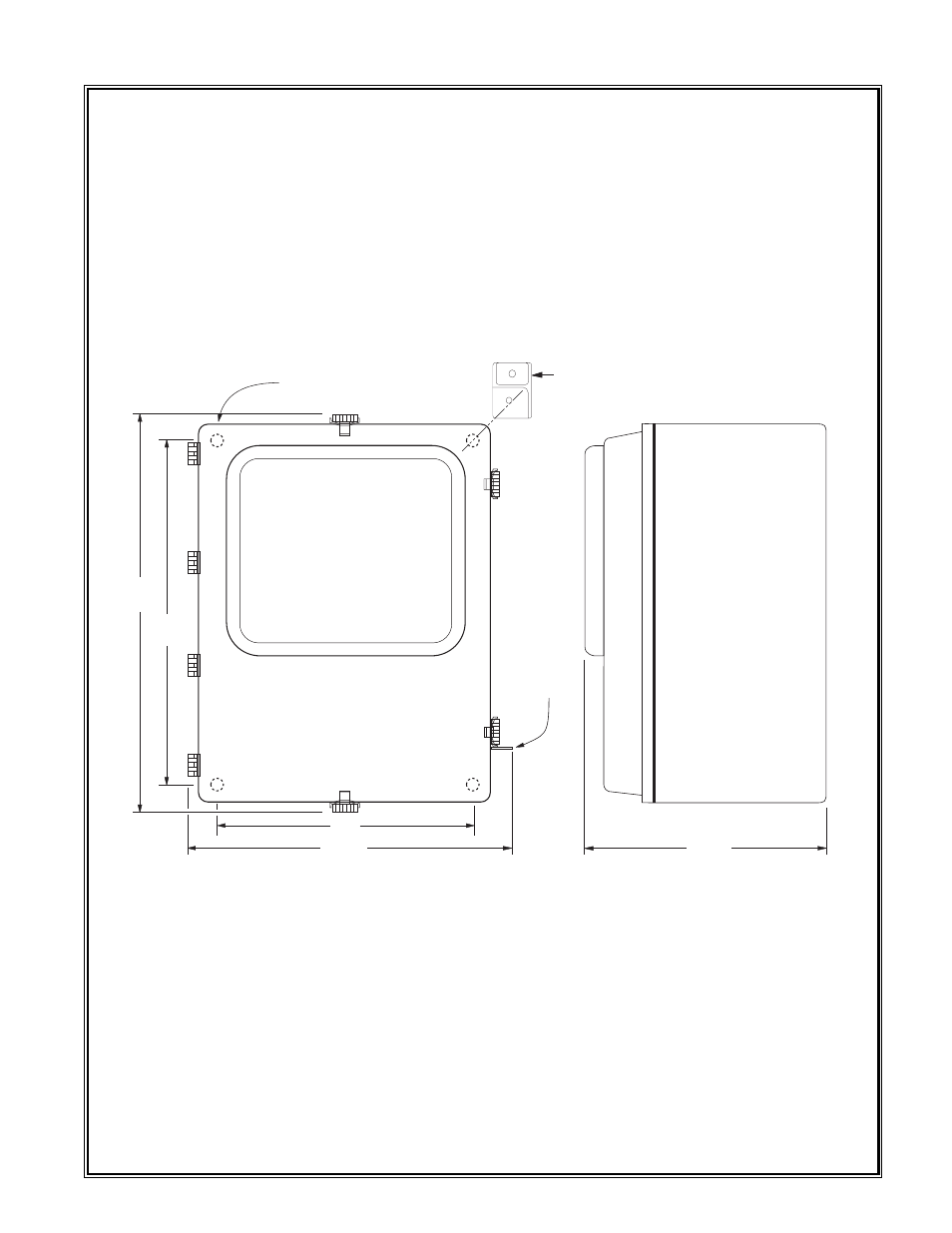
Step 1. Securely mount the 610A-FB enclosure (see figure 4).
Step 2. Connect 117 VAC input wiring to the lugless terminal strip (labeled AC IN) on the controller mother
board as detailed in figure 1. Line power current load is maximum 2 amps.
Step 3. Connect the 24 VDC standby battery to the lugless terminal strip (labeled DC IN) on the controller
mother board as detailed in figure 1. The DC current load is a maximum 3 amps.
Caution: Observe correct polarity when terminating all input / output field wiring. Failure to do so may
result in circuit damage on power up.
Step 4. If applicable, connect a normally open momentary remote mounted switch to the lugless terminal
strip (labeled RESET) located on the controller mother board as detailed in figure 1.
Detcon Model 610A-FB Gas Detection System PG.6
14.75"
17.25
10"
13.25"
PADLOCKING
LATCH
.31" DIA. MOUNTING HOLE
.56" DIA. COUNTERBORE
9.65
DIMENSIONS WITH MOUNTING FOOT: WIDTH - SAME AS STANDARD;
HEIGHT - 18.75"
MOUNTING HOLE DIMENSIONS (CENTER TO CENTER):
VERTICLE - 17.25
HOROZONTAL - 10.5
Figure 4 - Dimensions/Mounting Detail