11 2 m m, Figure 2 - multiple alarm relay circuit – Detcon 610A-FB User Manual
Page 4
1
1..2
2 M
M
U
UL
LT
TIIP
PL
LE
E
A
A
L
LA
AR
RM
M
R
R
E
EL
LA
AY
Y
C
C
IIR
RC
CU
UIIT
T
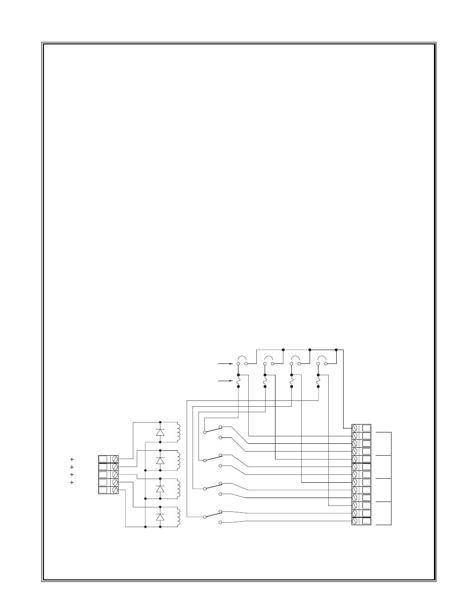
A multiple alarm relay circuit (figure 2) mounted on the controller mother board is provided with each
Detcon Model 610A-FB. The alarm circuit consists of 4 interposing relays (contacts are rated 8 amp @ 117
VAC / 5 amp @ 30 VDC) with 24VDC coils as standard. Other coil voltage ratings must be specified at time
of order. The alarm circuit can be configured to output Form C dry contacts (common, normally open and
normally closed), AC power or DC power. A 5 amp microfuse is provided for each relay and is configured in
series with the common pole of its respective relay. This configuration is functional regardless of whether
Form C dry contacts, AC power or DC power outputs are used.
An In/Out termination is provided for applying AC or DC power into any one of the interposing relays. A
gold plated jumper tab is used to apply the in/out power option to its corresponding relay, thus the 4 relays
may be used in a combination of Form C dry contacts and VDC outputs or Form C contacts and VAC out-
puts.
The terminations labeled "Alarm Coil Power" located to the left of the alarm circuit are used only for coil
power. The "+" termination may be used to provide for various relay logic through the Form C dry contacts
of each individual Model 10A channel located on the controller mother board directly above the alarm cir-
cuit card. The "-" termination should be wired into the common termination (shown by a common symbol)
located on the left of the alarm circuit board.
The terminations labeled "Alarm Power" located to the far left of the unit are used for providing power to
the In/Out termination on the alarm circuit card. As can be seen in the 610A-FB schematic / wiring diagram
(figure 3), the alarm power terminations for AC come directly from the AC input terminals located above on
the controller mother board. The same is true of the DC power terminations. Note: DC power used to drive
alarms must be obtained through a remote DC power source. The remote DC power source should be termi-
nated to the terminals labeled "DC IN" located on the controller mother board. The "DC IN" terminations
function as both an alternative DC source used to power the 610A-FB as well as provide power for DC
alarms. The 610A-FB power supply is not capable of providing power for alarm devices.
Detcon Model 610A-FB Gas Detection System PG.4
COIL #4
COIL #3
COIL #2
COIL #1
COMMON
#4
#3
#2
#1
#4
#3
#2
#1
IN / OUT
COM
N.C.
N.O.
COM
N.C.
N.O.
COM
N.C.
N.O.
COM
N.C.
N.O.
#4
#3
#2
#1
I/O JUMPERS
5 AMP MICRO FUSE
Figure 2 - Multiple Alarm Relay Circuit