Detcon DM-400IS User Manual
Page 18
NOTE 2: The test gas should be delivered at a controlled f low rate of 500 ml/min. Flow rates below 500 ml/m may
cause inaccurate readings and are not recommended.
3.6.2 Span Calibration
1)
Declassify the area around the sensor.
2)
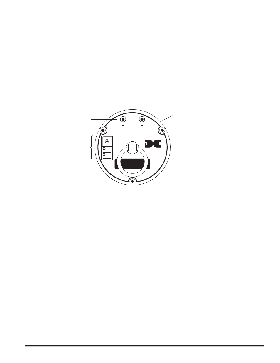
Remove the junction box cover.
3)
Measure the voltage between signal test points. If necessary (outside the range of 38 to 42 mV DC), adjust the
“zero” potentiometer to achieve a reading of 40 mV DC. NOTE: Be sure there is no target gas present in the back-
ground or apply a zero gas standard to perform a zero calibration.
4)
Attach the calibration adapter to the sensor housing.
5)
Apply the test gas at a controlled flow rate of 500 ml/m. Wait 2-3 minutes for signal stability.
6)
Set the “coarse” span rotary switch to the position that causes the signal to read closest to 120 mV DC.
7)
Use the “fine” span potentiometer to adjust the signal to a reading of 120 mV DC. Note: if a signal of 120 mV DC cannot
be reached by turning the “fine” span potentiometer, turn the “coarse” span rotary switch up or down one position as nec-
essary, then make final adjustments with the “fine” span potentiometer.
8)
Remove the gas standard and calibration adapter. Observe that the signal decreases to
≈
40 mV DC within 3-5 min-
utes. Make any needed adjustments to the “zero” potentiometer.
NOTE: Because there is interaction between the span and zero functions, it may be necessary to repeat steps 4 through 8.
Calibration is complete. Replace the splash guard and junction box cover.
3.6.3 Calibration Notes
Detcon Model DM-400IS series sensors provide a signal output of 4-20 mA DC which corresponds to 0-100% of scale. This
signal is ref lected by a 40-200 mV DC voltage across the signal test points. Thus, if a sensor’s full scale range is 0-100ppm,
then the signal output will move by .16 mA (or 1.6 mV across the signal test points) for each 1ppm of movement.
To determine the signal movement per ppm, for other ranges, divide the full scale signal of 160 mV by the number of ppm in
the range of detection. For example, if a sensor’s range of detection is 0-25ppm, you would divide 160 mV by 25 to arrive at
the figure of 6.4 mV per ppm. This signal will begin its movement from a base line of 40 mV. Below is a listing of sample
detection ranges and the signals (as read from the signal test points) they will provide at different gas concentrations.
DM-400IS Toxic Gas Sensors PG.18
T E
X
A
S
H
O
US
TO
N
SIGNAL
Model DM-4xx
ZERO
FINE
COARSE
Gas Sensor
detcon inc.
UNIVERSAL
TRANSMITTER
0123
4
5
678
9A
B
C
D
E
Span Adjustments
Plug-in Transmitter Circuit
Signal Test Points