Detcon Remote Cal / Remote Sensor Separation Kit User Manual
Page 4
Remote Cal Kit
Remote Cal Kit
Rev. 2.1
Page 2 of 2
6.
Connect ¼” Teflon sample tubing to the calibration port on the splashguard (Figure 2). Push the tubing
onto the calibration port until it seats completely.
7.
TP & FP series sensors only: Reference the “Remote Mount Applications” section of the sensor
instruction manual for details on setting sensor heater/bridge voltages at the remote sensor location. Set
the heater/bridge voltage appropriately.
8.
Calibrate the sensor to insure proper operation.
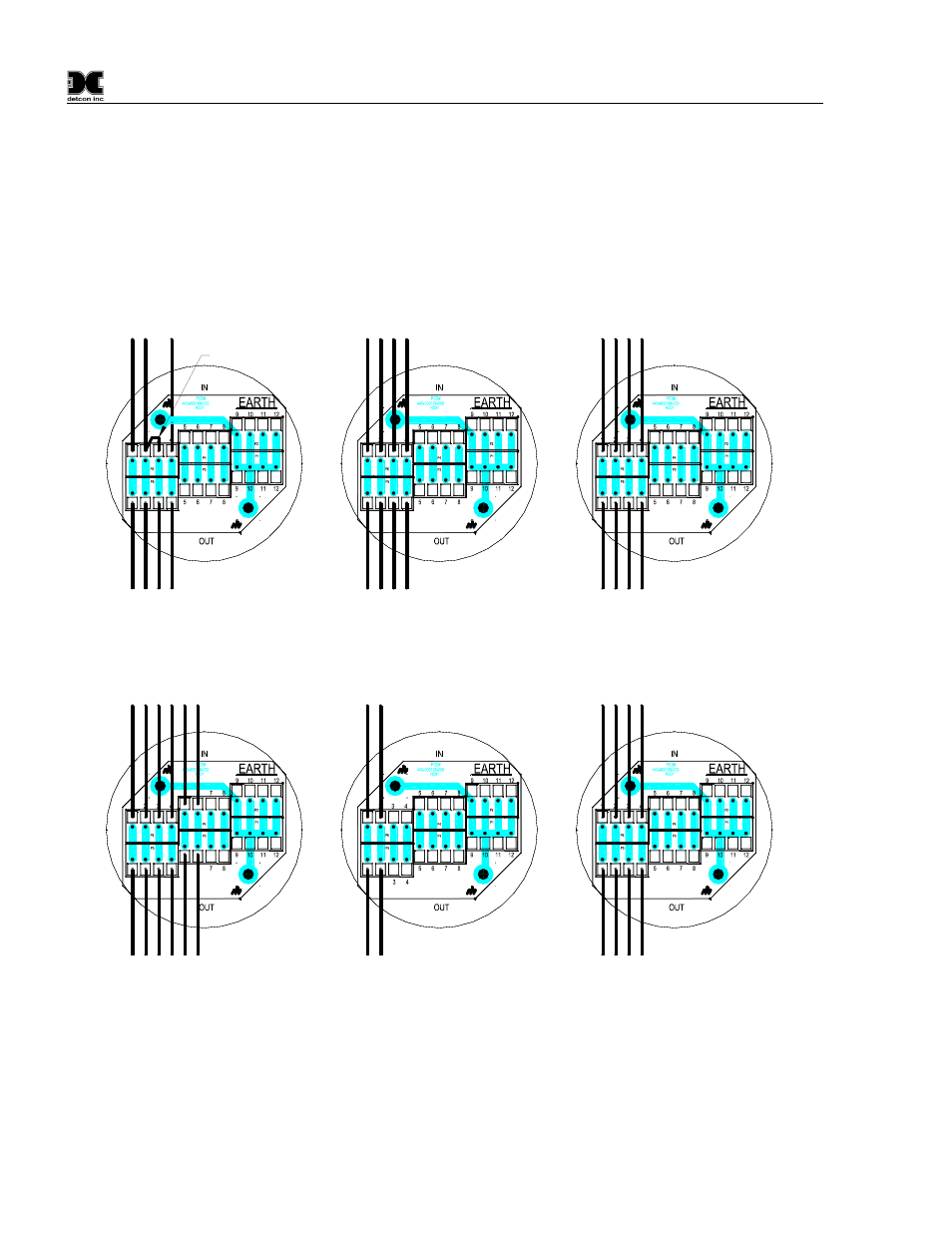
NOTE: cut yellow wire off
if used with DM-500IS or
DM-600IS Sensors.
Wht
Blk
Yel
Blu
Wht
Blk
Blu
To FP Sensor
To Transmitter
FP Combustible Series
Install Jumper
Red
Brn
Wht
Blk
Re
d
Brn
Blk
To IR Sensor
To Transmitter
IR Infrared Series
Yel
Blu
Wt
h
Blu
Yel
Wht
Blu
Wht
Blu
To Transmitter
Wht
Blk
Yel
Blu
Wht
Blk
Blu
To IS Sensor
To Transmitter
DM Oxygen Series
IS Toxic Series Sensors
Yel
To O2 Sensor
Wht
Bl
k
Ye
l
Bl
u
Wht
Blk
Blu
To TP Sensor
To Transmitter
Wht
Bl
k
Ye
l
Bl
u
Wht
Blk
Blu
To PI Sensor
To Transmitter
Yel
TP Solid State H
2
S Series
PID Universal VOC Sensor's
Yel
Figure 3 Remote Condulet Wiring