Installation, Figure 5 dimensional, Figure 6 customer wiring – Detcon A1-DV2 User Manual
Page 8: 0 installation
A1-DV2
2.0 Installation
NOTE: The alarm station is a precision instrument and care should be taken when handling it.
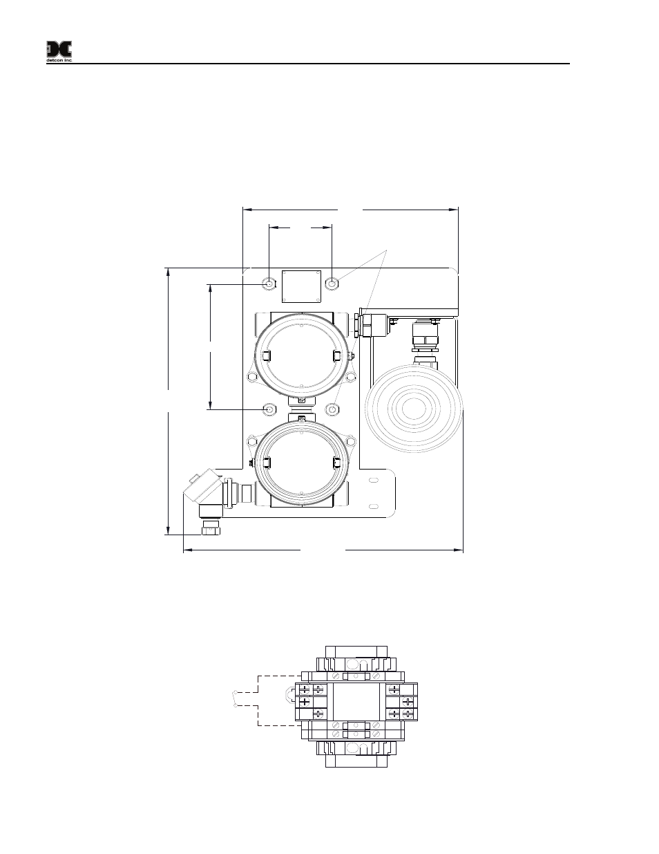
The Wireless A1-DV2 Alarm Station is made to be mounted on a 2” or 3” diameter pipe. Two 3” U-bolts with
hardware are provided for mounting. The location for mounting the wireless alarm station should be carefully
selected. Occasional access to the unit will be necessary for battery replacement and maintenance.
3.5"
17"
Typ.
15.6" Typ
7.8"
Mounting U-Bolts
12.0"
Figure 5 Dimensional
The unit is provided with terminal blocks and a relay for customer wiring. Customer to provide dry contact
closure and wiring for alarm activation. Connect the dry contact wiring to the provided terminal blocks shown
in Figure 6.
Customer
Provided Alarm
Enable Dry
Contacts
13
Figure 6 Customer Wiring
A1-DV2 with Battery Manual
Rev.0.0
Page 4 of 8
- 12B (16 pages)
- FL-10 (7 pages)
- 10C Facilities (18 pages)
- 10C (29 pages)
- 10B (10 pages)
- 1212-N4X (9 pages)
- 812-N4X (9 pages)
- 1212B (5 pages)
- 612B (5 pages)
- 1610-N4X (28 pages)
- 1010-N4X (14 pages)
- 610-N4X (12 pages)
- 1610-N1 (4 pages)
- 810-N1-24VDC (10 pages)
- 410-N1-24VDC (4 pages)
- MCX-32-N1P (55 pages)
- RD-64X-N4X (41 pages)
- 880RA-N4X (36 pages)
- 880RA-N4X (23 pages)
- 880A-N1R (45 pages)
- 880A-N4X (50 pages)
- 880A-N4X (43 pages)
- X40-08-N4X (70 pages)
- 240 (33 pages)
- SW-AV1-N4 (12 pages)
- SW-AV2-DV1 (12 pages)
- A1V1 (9 pages)
- RXT-300 (47 pages)
- RXT-320 (31 pages)
- CXT-N4X (28 pages)
- SW-HMI-32-N4X (24 pages)
- SW-V1-DV2 (11 pages)
- SW-AV1-DV1 (14 pages)
- SW-AV2-DV2 (12 pages)
- SW-AV1-DV2 (12 pages)
- SmartWireless CX (33 pages)
- SmartWireless CXT (49 pages)
- CX-IR (38 pages)
- CX-DM (44 pages)
- CXT-IR (48 pages)
- CXT-DM (56 pages)
- P-1000 (28 pages)
- 1000 (32 pages)
- 1000_CO2 (32 pages)
- 1000_H2S (34 pages)