Figure 4 motherboard wiring diagram – Detcon 1010-N4X User Manual
Page 9
Model 1010-N4X
1010-N4X Instruction Manual
Rev. 2.1
Page 5 of 10
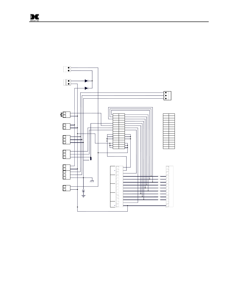
2. Refer to installation and wiring detail of remote mount sensor assemblies as detailed in the Sensor
Instruction Manual. Terminate field wiring from sensors on the 1010-N4X motherboard. Terminals
are labeled “Sensor” (mA, + and –, Figure 4).
3. If applicable, terminate the discrete 4-20mA outputs to external device(s). Terminals are labeled “4-
20 Out” (+ and –, Figure 4).
A1
C1
C2
A2
A3
C3
C4
A4
A5
C5
A6
C6
C7
A7
A8
C8
C9
A9
A10
C10
A11
C11
C12
A12
A13
C13
C14
A14
A15
C15
A16
C16
A2-COM
A2-NC
A2-NO
FLT-COM
FLT-NC
FLT-NO
4-20 OUT
4-20 IN
--
XM+
XM+
XM+
--
VDC+
VDC+
VDC+
A1-NO
A1-NC
A1-COM
--
485-A
RST
485-S
485-B
--
XM-
XM-
XM-
--
VDC-
VDC-
VDC-
GND
ALM COIL
-
+
RS-485
ALM POWER
L1
N
+
-
N
GND
A(+)
B(-)
Shld
VDC IN
ALM RESET
L1
-
+
VAC IN
P14
P15
P16
P17
P18
P20
PS DC
-
+
P2
BRKR
P1
1
2
1
2
1
2
1
2
1
2
3
1
2
3
1
2
1
2
3
4
5
1
2
3
4
5
6
7
8
9
10
11
12
13
14
P11
1
2
3
4
5
6
7
8
9
10
11
12
13
14
JP1-JP5
A
B
C
D
E
F
G
H
I
P12-P20
mA
NC
+
COM
NC
NO
NO
NC
NO
COM
COM
+
ALM 1
OUT
4-
20
F
A
UL
T
SENS
O
R
ALM2
A1
C1
C2
A2
A3
C3
C4
A4
A5
C5
A6
C6
C7
A7
A8
C8
C9
A9
A10
C10
A11
C11
C12
A12
A13
C13
C14
A14
A15
C15
A16
C16
CH1
CH2-CH10
RS-485
Shield
to Gnd
Earth
Ground
Tie to
Chassis
CH1
CH2-CH6
Typical
Jumpers
D2 6A 50V
D1 6A 50V
N
L1
GND
PS VAC
P3
1
2
3
P19
Figure 4 Motherboard Wiring Diagram
4. If applicable, terminate the RS-485 serial output to external device(s). Terminals are labeled “RS-
485” (A+, B–, and Shield, Figure 4). If applicable, terminate RS-485 Shield to Earth Ground via the
jumper tab located to the left of the RS-485 terminals. Place the jumper on the bottom 2 contacts to tie
RS-485 shield to Earth Ground or place the jumper tab on the top two terminals for storage.
5. If applicable a Remote Reset Switch can be utilized by connecting a Momentary, Normally-Open
Switch to P4 (ALM RESET).
6. Earth Ground can be connected to the ground point located in the lower left quadrant of the
motherboard.