Detcon PI-500 User Manual
Page 17
3.5 S
TART
U
P
Upon completion of all mechanical mounting and termination of all f ield wiring, apply system power and observe the
following normal conditions:
a)
PI-500 “Fault” LED is off.
b)
A temporary upscale reading will occur as the sensor powers up. This upscale reading should clear to “0” ppm with-
in approximately 5-10 minutes of turn-on, assuming there is no gas in the area of the sensor.
NOTE 1: If the display contrast needs adjustment, refer to section 3.11.
NOTE 2: If the sensor does not clear to zero after 15 minutes of warm-up, there may be target VOC gases present in the area.
3.5.1 Initial Operational Tests
After a warm up period has been allowed for, the sensor should be checked to verify sensitivity to its target gas.
Material Requirements
*
Detcon PN 943-000006-132 Calibration Adapter
*
Span gas containing isobutylene in air. It is recommended that the target gas concentration be 50% of scale at a con-
trolled f low rate of 200 cc/min. For example, a Model PI-500 sensor in the range 0-100ppm would require a test gas of
50ppm isobutylene. For a sensor with a range of 0-10ppm a test gas of 5ppm is recommended, etc. Other concentra-
tions are acceptable as long as they are between 10%-90% of full-scale range.
a)
Attach the calibration adapter to the sensor housing. Apply the test gas at a controlled f low rate of 200 cc/min.
Observe that the LCD display increases to a level of ±10% of applied concentration.
b)
Remove the test gas and observe that the LCD display decreases to “
0 PPM
”.
Initial operational tests are complete. Detcon PID gas sensors are pre-calibrated prior to shipment and will, in most
cases, not require signif icant adjustment on start up. However, it is recommended that complete zero and span calibra-
tions be performed within 24 hours of installation. Refer to calibration instructions in later text.
PI-500 Toxic Gas Sensors PG.17
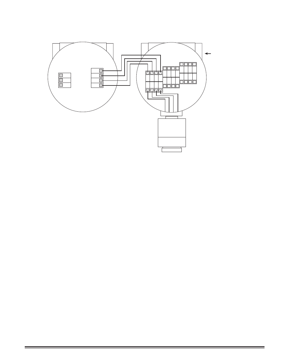
1 2 3 4
W
H
T
B
L
K
Y
E
L
B
LU
Remote Transmitter
PI-500-RT
Remote Sensor
PI-500-RS
WHT
BLK
YEL
BLU
Plug unused port
with 3/4 NPT plug.
Figure 4