WEN 70716 10 inch Sliding Compound Miter Saw User Manual
Page 11
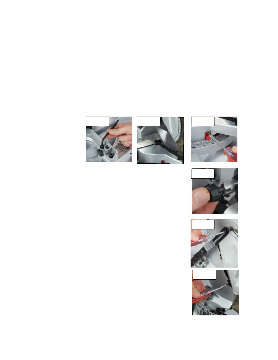
Setting the fence square with the table
1. Make sure that the power cord is removed from the power source.
2. Push the saw arm down to its lowest position and engage the release knob (Fig. 24) to hold the saw arm in the
transport position.
3. Loosen the miter lock (Fi . 15).
4.
the table until the o
ositioned at 0º.
5. Tighten the miter lock (F . 15).
6. Using the 6mm hex key ovided, loosen the four screws securing the fence to the base (Fig. 21).
7. Place a square against th
ade (Fig. 22).
8. Adjust the fence until it is square with the blade.
9. Tighten the screws sec
10. Loosen the scr
scale (Fig. 23) and adjust it so that it accurately indicates the
zero position on
11. Retighten the s
hanging a blade
ANGER! Never try to use a
ger than the statedc
of the saw. It
ight come into contact with theblade guards. Never use a blade that is too thick to
llow theouter blade washer to engage with the flats on the spindle.
will prevent the blade screw from properly securing the blade on the spindle. Do
ot use the saw to cut metal or masonry. Ensure that any spacers and spindle
ngsthat may be required suit the fitted spindle and blade.
. Make sure that the power cord is removed from the power source.
. Push down on the operating handle (1) and pull the release knob (Fig. 24) to
aw arm. The release knob (Fig. 24) can be turned so that it is
position.
he arbor bolt
in the upward position,
o loosen and remove the arbor bolt (loosen in a
a left-handed thread) (Fig. 29).
contact
g
Rotate
p inter is p
ig
pr
e fence and alongside the bl
uring the fence.
ew holding the pointer of the miter
the miter scale (Fig. 23).
crew securing the miter scale pointer.
C
D
blade lar
apacity
m
a
It
n
ri
1
2
disengage the s
held in the retracted
3. Raise the saw arm to its highest position.
4. Using a screwdriver loosen and remove the screw that secures the guard
retraction arm to the rotating blade guard (Fig. 25).
. Using a screwdriver loosen and remove the screw that secures t
5
cover (Fig. 26).
6. Pull the rotating blade guard down then swing it up together with the arbor
bolt cover. When the rotating blade guard is positioned
Fig. 21
Fig. 22
Fig. 23
Fig. 24
Fig. 25
Fig. 26
it is possible to access the arbor bolt (Fig. 27).
7. Hold the rotating guard up and press the spindle lock button (Fig. 28). Rotate
the blade until the spindle locks.
8. Use the 6mm hex key provided t
clockwise direction as the blade screw has
9. Remove the flat washer, the outer flange washer and the blade.
10. Wipe a drop of oil onto the inner flange and the outer flange where they
the blade.
11. Fit the new blade onto the spindle taking care that the inner flange sits behind
the blade (Fig. 30).
11