WEN 70716 10 inch Sliding Compound Miter Saw User Manual
Page 10
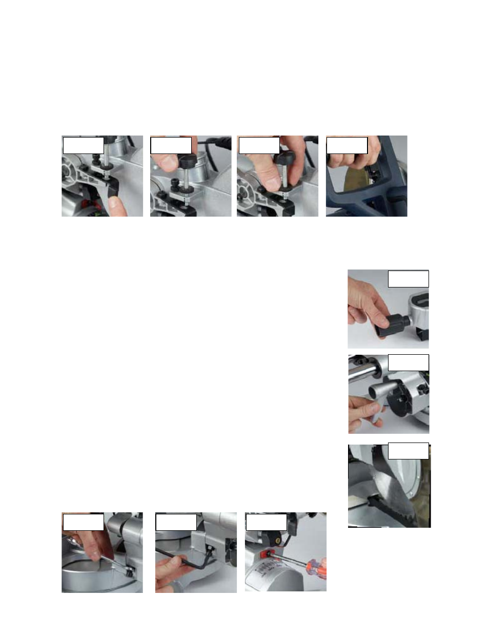
Trench depth adjustment
nching stop permits the saw blade to cut right through a workpiece. When the saw
e
Turning on and off
1. Pull in switch trigger to startthe unit (Fig. 14).
To turn the saw off releasethe ON/OFF trigger switch.
g the table square with the blade
. Make sure that the power cord is removed from the power source.
Push the saw arm down to its lowest position and engage the release knob(Fig. 2)
to hold the saw arm in the transport position.
. Loosen the miter lock(Fig. 15).
Rotate the table until the pointer is positioned at 0º.
lock (Fig. 15).
arm at 0º bevel (leaving the blade
).
e blade (Fig. 17).
te.
Make sure that the square contacts the flat part ofthe saw blade, not the teeth.
e blade-to-tablealignment at several points.
blade shouldbe parallel.
) with the 6mm hex key to bring the
scale and adjust the position
In its normal position, the tre
arm is lifted, the trenching stop can be moved to the left so that the trenching depth adjustment screw contacts th
stop as the saw arm is lowered. (Fig.11).This restricts the cut to a specific “trench” in the workpiece. The depth of
the trench can be adjusted with the trenching depth adjustment screw (Fig. 12) and locked in position with the
trenching depth lock nut(Fig. 13).
2.
Settin
1
2.
3
4.
5. Tighten the miter
6. Loosen the bevel lock (Fig. 16) and set the saw
at 90º to the miter table). Tighten the bevel lock (Fig. 16
. Place a set square against the table and the flat partof th
7
No
8. Rotate the blade by hand and check th
9. The edge of the set square and the saw
10. If the saw blade angles away from the set square,adjust as follows.
11. Use a 13mm wrench or adjustable wrench to loosen thelock nut securing the
0°bevel adjustment screw(Fig. 18). Also, loosenthe bevel lock (Fig. 16).
crew ( Fig. 18
12. Adjust the 0° bevel adjustment s
saw blade into alignment with the square (Fig. 19)
pointer of the bevel
13. Loosen the 2 screws holding the
of the pointer so that it accurately indicates zero on the scale (Fig. 20). Retighten
the screw.
14. Retighten the bevel lock (Fig. 16) and the lock nut securing the 0° bevel
adjustment screw (Fig. 16).
te
No .
The above procedure can also be used to check theangle of the saw blade to the
Fig. 11
Fig. 12
Fig. 13
Fig. 14
Fig. 15
Fig. 16
Fig. 17
table at the 45º bevel angle.
Fig. 18
Fig. 19
Fig. 20
10