Enjoy your mount – Video Mount Products IWB-1B User Manual
Page 6
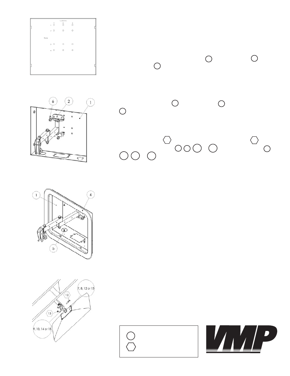
Step 13: Attaching the trim cover
Step 14: Connecting the mounting
plate to the pivot bracket
Step 12A: Mount support location diagram
Step 12B: Attaching the mount
supports to the wall box
WARNING: The installer of these products must verify that the mount-
ing surface, ceiling or wall, will safely support the combined weight
of all attached equipment and hardware. Video Mount Products will
not be held liable for the improper use or installation of its products.
Enjoy Your Mount!
1
2
6
Step 13
Attach the trim cover to the wall box using the M4 screws
provided with the IWB-1.
Step 14
Attach your LCD to the LCD-1 or LCD-2537 arm using the M6 screw
LCD-1 or LCD-2537 and nylon nut LCD-1 or LCD-2537 to at-
tach the mounting plate , , or to the pivot bracket ,
, or .
Please verify that all nuts and screws are completely and securely
tightened.
1
4
5
12
8
7
13
12
13
9
15
14
10
Step 12
Determine if you want the arm to fold left or fold right. If you want
the arm to fold right you use the fi rst and second column of holes. If
you want the arm to fold left you use the second and third column
of holes. Attach the mount supports to the wall box using
the M8 screws . Note: For the LCD-2537 you should use the fi rst
and third rows of holes. For the LCD-1 you should use the second
and forth rows of holes.
Key:
IWB-1
LCD-1 or LCD-2537
VIDEO MOUNT PRODUCTS