Video Mount Products IWB-1B User Manual
Page 5
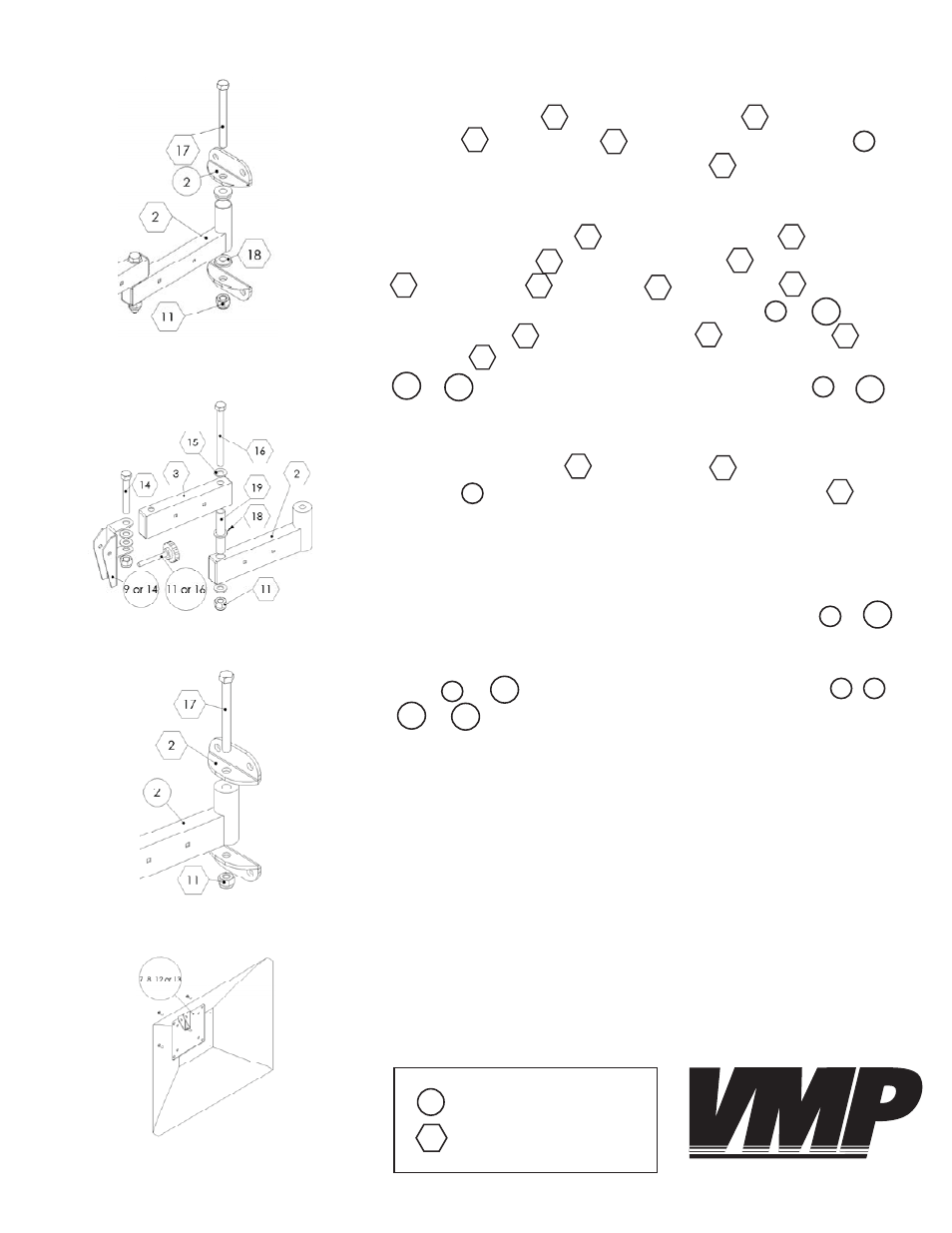
Step 9
Insert the longer spacer into the rear force arm and attach
the front force arm to the rear force arm using the metal pin
, 3/8” washers , ½” washer and nylon nut . Attach the
LCD-2537 pivot bracket provided with the IWB-1 or to the
front force arm using the 3/8” screw , 3/8” washers and
nylon nut . Insert the adjustable screw provided with the IWB-1
or into the threaded hole of the pivot bracket or .
Step 10: Attaching the mount supports
Step 11: Attaching the mounting plate
Step 10
Use the long 3/8” bolt and nylon nut to attach the mount
supports to the bottom and top of the rear force arm .
Step 11
Determine the VESA mounting hole pattern for your LCD. If the hole
pattern is either 75 mm x 75 mm (about 3” x 3”) or 100 mm x 100 mm
(about 4” x 4”) then you will use the small mounting plate or .
If the hole pattern is either 100 mm x 200 mm (about 4” x 8”) or 200
mm x 200 mm (about 8” x 8”) then you will use the large mounting
plate or . Attach the appropriate mounting plate , ,
or using the screws provided with the LCD-1 or LCD-2537.
17
2
2
13
11
8
12
7
8
7
13
12
9
14
19
2
3
2
16
15
18
11
3
14
15
11
16
11
9
14
Step 9: Assembling the LCD-2537 arm
Step 8: Attaching the mount supports
Step 8
Insert the end plugs into the rear force arm and use the long
3/8” bolt and nylon nut to attach the mount supports to
the bottom and top of the rear force arm . Proceed to step 11.
2
18
2
17
11
2
Key:
IWB-1
LCD-1 or LCD-2537
VIDEO MOUNT PRODUCTS