Warning – Video Mount Products IWB-1B User Manual
Page 4
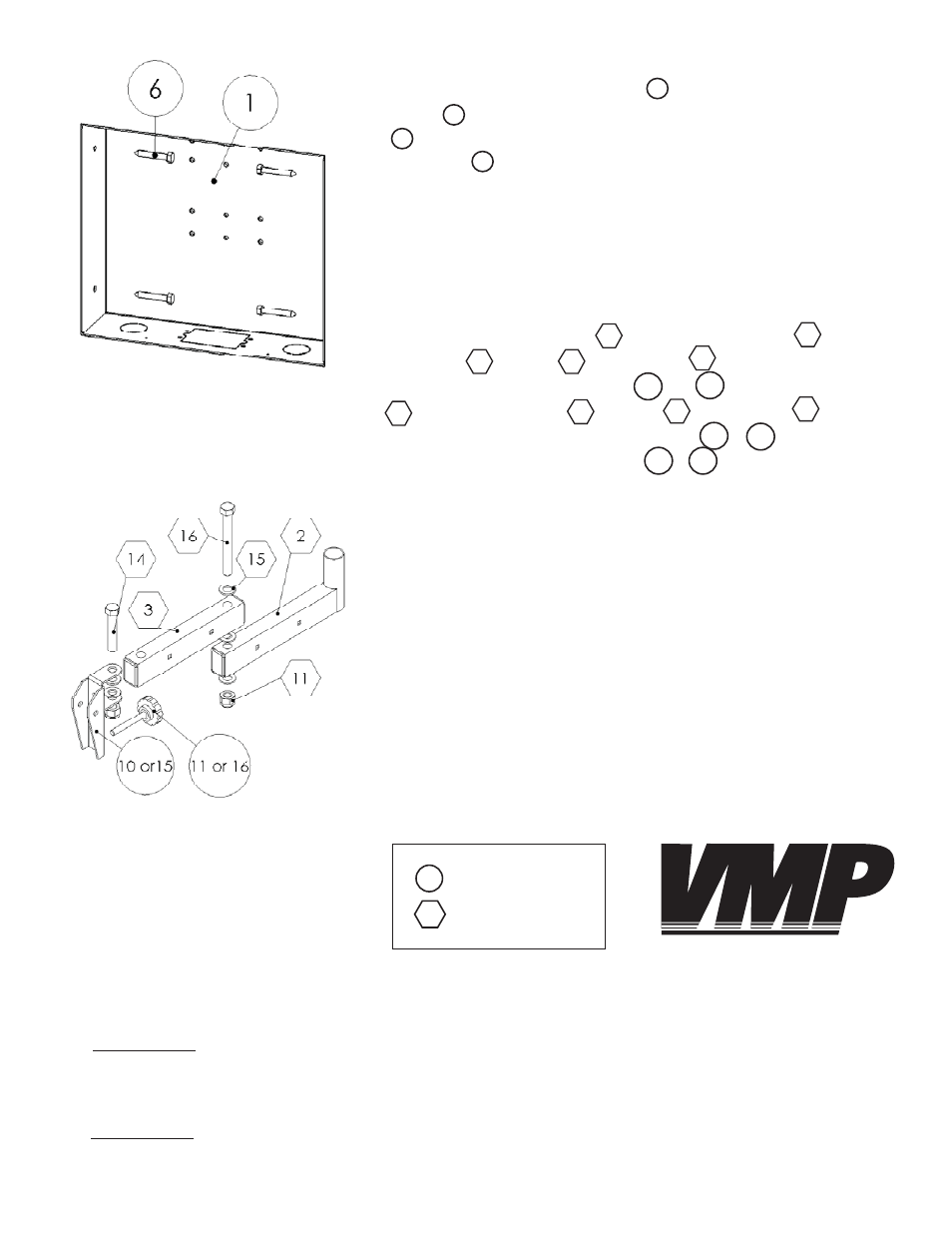
** Step 6 **
Pre-drill and attach the wall box to the studs using the M8 lag
crews provided. Note: It is very important the front of the box
is as fl ush as possible with the wall as to insure a proper fi t for the
trim cover .
If you are installing a LCD-1 into the IWB-1 proceed to the next step.
If you are installing a LCD-2537 into the IWB-1 proceed to step 9.
Step 7
Attach the front force arm to the rear force arm using the
metal pin , washers and nylon nut . Attach the LCD-1 pivot
bracket provided with the IWB-1 or to the front force arm
using the 3/8” screw , washers and nylon nut . Insert the
adjustable screw provided with the IWB-1 or into the thread-
ed hole of the pivot bracket IWB-1 or .
Step 6: Lagging the wall box
into the studs
Step 7: Assembling the LCD-1 arm
15
10
1
6
1
11
3
2
16
15
3
14
15
11
16
11
15
10
**
WARNING:
ELECTRICAL SHOCK HAZARD! CUTTING OR DRILLING INTO ELECTRICAL WIRES OR CABLES
CAN RESULT IN DEATH OR SERIOUS PERSONAL INJURY! Always make sure the area you are preparing to cut
or drill into is completely clear of electrical wires before you proceed in order to prevent injuries.
**
WARNING:
EXPLOSION AND FIRE HAZARD! CUTTING OR DRILLING INTO GAS PLUMBING CAN RESULT IN
DEATH OR SERIOUS PERSONAL INJURY! Always make sure the area you are preparing to cut or drill into is com-
pletely clear of gas, water, waste or any other plumbing before you proceed in order to prevent injuries.
Key:
IWB-1
LCD-1
VIDEO MOUNT PRODUCTS
4