Belt and pulley alignment – Triangle Engineering of Arkansas FHI SERIES PANEL FANS User Manual
Page 2
INSTALLATION
INSTALLING THE PANEL FAN: Wall openings must be square and
should be 1/4" to 1/2" greater than the outside dimension of the pane
START-UP AND OPERATION
Careful inspection should be made before start-up. All motor bear-
ings should be properly lubricated, all fasteners should be securely
tightened. Impeller should be rotated by hand to insure free move-
ment. (NOTE: Before placing hand on propeller, or V-belts local out
primary and secondary power source). Check all set-screws and keys.
Tighten where necessary.
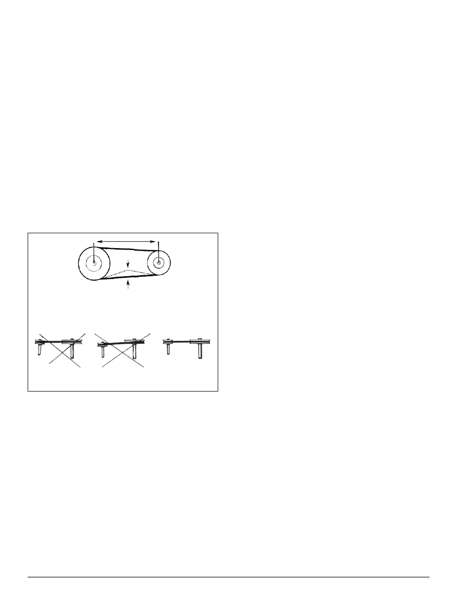
The condition of V-belts and the amount of belt tension should
be checked prior to start-up. When it becomes necessary to adjust
belt tension, do not over-tighten as bearing damage will occur.
Recommended belt tension should permit 1/64" per inch of span
deflection of the belt on each side of the belt measured halfway
between the pulley centerline. Extreme care must be exercised when
adjusting V-belts as not to misalign the pulleys. Any misalignment
will cause a sharp reduction in belt life and will also produce squeaky,
annoying noises. On units equipped with 2 or 3 groove pulleys, adjust-
ments must be made so that there is equal tension on all belts (see
drawing below).
WARNING - Whenever belts are removed or installed, never force
belts over pulleys without loosening motor first to relieve belt ten-
sion. The fan has been checked at the factory prior to shipment for
mechanical noises. If mechanical noise should develop, then some
suggestions are offered here as a guide toward remedying the cause.
1. Check rotating members for adequate clearance.
2. Check proper belt tension and pulley alignment.
3. Check installation and anchoring.
4. Check fan bearings.
The inlets and approaches to the exhauster should be free from
obstructions. To assure maximum air movement an adequate supply
air must be available.
Power lines compatible with the motor requirements are brought
up from an electrical source to the unit. A generous amount of slack in
power lines should be provided to allow for motor deflections and to
permit movement of motor for belt-tension adjustments. Motor must
be securely and adequately grounded. Protect power lines from sharp
objects. Do not kink power line or permit it to contact hot surfaces,
chemicals, grease or oil.
Before putting any fan into operation, the following check list
should also be completed:
a. Lock out primary and secondary power source. b. Make sure
installation is in accordance with manufacturer’s instructions.
c. Check and tighten all fasteners. d. Spin propeller to see if rotation
is free and does not bind or rub.
e. Check all set-screws and keys and tighten if necessary.
f. Check V-belt or direct drive coupling for alignment. Use rec-
ommended belt tension.
g. Check V-belt for proper sheave selection and make sure they are
not in reverse position.
h. Make sure there is no foreign loose material in duct work leading
to and from fan or in the fan itself.
j. Properly secure all safety guards.
k. Secure all access doors to fan and duct work. I. Check line voltage
with motor nameplate.
m. Check wiring. (NOTE: On single phase motors, the terminal block
must be set up in accordance with the nameplate instructions
and/or wiring diagram. The set-up must match the line voltage.
If the motor is 3 phase, the winding leads must be grouped and
connected as shown on the wiring diagram. The line voltage
must correspond with proper grouping of motor leads. On 2-
speed motors the wiring diagram must be followed precisely or
serious motor damage will occur.)
Switch on electrical supply and allow fan to reach full speed. If
heater elements are tripping out the starters, the following items
should be investigated:
Is the heater element the correct size for the motor?
Is the starter located in a high ambient temperature?
Is the propeller rotating in the correct direction?
Is the line voltage excessively low?
Is the motor wired properly to suit the line voltage?
Check carefully for:
1. Correct rotation of the propeller. (NOTE: Incorrect rotation over-
loads motor severely and results in serious motor damage. To
change rotation of 3 phase units, simply interchange any two of
the three line leads. On single phase units, change the terminal
block set-up following the wiring diagram.)
2. Check motor and bearing temperatures so that they are not
excessively hot. (NOTE: Use care when touching the exterior of
an operating motor. Modern motors normally run hot. They are
designed to operate at higher temperatures. This is a normal con-
dition, but they may be hot enough to be painful or injurious to the
touch.) If any problem is indicated, SWITCH OFF IMMEDIATELY,
Lock out the electrical supply and check carefully for the cause of
the trouble and correct as needed. Even if the fan appears to be
operating satisfactorily, shut down after a brief period and check
all fasteners, set-screws and keys for tightness.
The fan may now be put into operation but during the first eight
(8) hours of running it should be periodically observed and checked
for excessive vibration or noise. At this time checks should be made
on motor input current and motor bearing temperatures to insure
they do not exceed manufacturer’s recommendations. After eight
hours of satisfactory operation, the fan should be shut down and the
electrical power locked out to check the following items and adjust if
necessary:
a. All set-screws, keys and fasteners.
b. Drive coupling alignment.
c. V-belt drive alignment.
d. V-belt tension.
*Deflection height h = 1/64" per inch of span (t)
BELT AND PULLEY ALIGNMENT
WRONG WRONG CORRECT