Important – Triangle Engineering of Arkansas CMPC User Manual
Page 2
DESCRIPTION
The HEAT BUSTER is a high volume portable fan
designed for heavy-duty use in factories, ware-
houses, laundries, garages, etc. lt is easily rolled to
various locations on sturdy 8-inch diameter wheels.
The unit is constructed of cold-rolled steel with a
powder coat finish. Guards are made of steel wire
and comply with OSHA guarding requirements. The
ON/OFF switch is conveniently mounted and guarded
on side of barrel.
GENERAL SAFETY INFORMATION
1. Your HEAT BUSTER fan will operate only on 115
Volt AC, 60Hz (cycle) current with a minimum of a
15 Amp circuit.
2. WARNING: To reduce the risk of electric shock,
DO NOT expose to water or rain. To guard against
electric shock while the fan is connected to power
source, DO NOT PERMIT fan to come in contact with
other grounded objects such as pipes, radiators,
ranges, etc.
3. DO NOT ABUSE POWER CORD. DO NOT pull on
cord to remove from electrical receptacle. Keep cord
away from heat, oil and sharp edges. Inspect cord
periodically and replace if damaged.
4. Disconnect the fan when not in use, before servicing
and cleaning and when repairing or replacing parts.
5. DO NOT carry or move the fan when connected
to power source. Be sure switch is in “OFF” position
prior to connecting to power source.
6. When the HEAT BUSTER is used out-of-doors with
extension cord, use only cord of proper size (Amp
rating), UL listed and with receptacle to accept three
prong grounded plug furnished on the fans power cord.
Only round jacketed extension cords should be used.
7. Before operating this fan, check for worn or dam-
aged parts and replace or repair as required. To avoid
risk of fire, electrical shock or other injury, discon-
nect from power source before servicing.
8. DO NOT operate the HEAT BUSTER near flamma-
ble liquids or in gaseous or explosive atmospheres
as sparks from motor may ignite fumes.
9. If the wire guards are removed, replace before
normal operation.
10. In case of power failure, turn off the fan at switch.
This will prevent motor burn out and/or unexpected
restarting.
ASSEMBLY
No assembly required
INSTALLATION
Simply locate fan in desired position, connect
power cord, and fan is ready for operation.
OPERATION
Your Heat Buster fan is turned ON or OFF with a
rocker switch located toward the top of the barrel. To
operate the single speed fan push the rocker switch
down on one side to turn the fan ON and down on
the opposite side to turn the fan OFF. To operate the
two speed fan push one side of the rocker switch
down for low speed and the opposite side down for
high speed. Place the rocker switch in the center
position to turn the fan OFF.
IMPORTANT:
READ INSTRUCTIONS CAREFULLY BEFORE ATTEMPTING
TO INSTALL, OPERATE OR SERVICE THIS FAN. FAILURE TO COMPLY WITH
INSTRUCTIONS COULD RESULT IN PERSONAL INJURY AND/OR PROPERTY
DAMAGE. RETAIN INSTRUCTIONS FOR FUTURE REFERENCE.
5
4
3
2
1
6
5
4
3
2
1
Switch
Switch
Motor
Motor
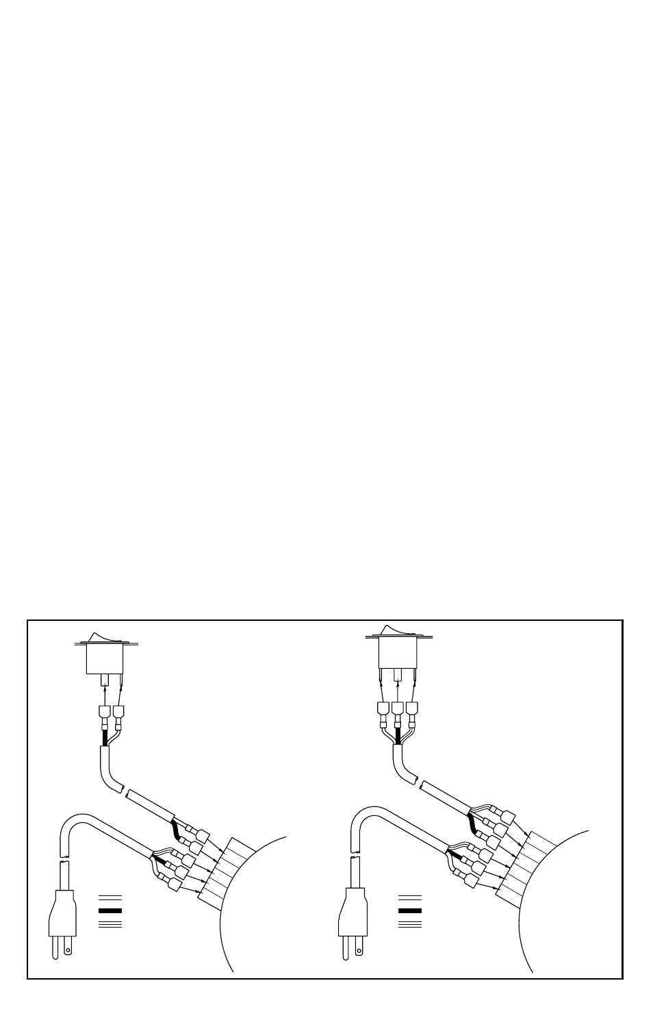
SPL 3613 and SPL 4213
Wiring Diagram
View Facing Motor Shaft
NOTE: Switch wires may be reversed
without affecting performance
SPL 3623 and SPL 4223
Wiring Diagram
View Facing Motor Shaft
White
Black
Green
White
Black
Green