Assembly of heavy-duty boltless rack – Tennsco Z-Line Heavy Duty Boltless Rack User Manual
Page 2
Tools Needed: A rubber mallet for seating the shelf supports. Two people are recommended for assembly.
Approximate assembly time: 15 to 30 minutes per section.
ASSEMBLY OF HEAVY-DUTY BOLTLESS RACK
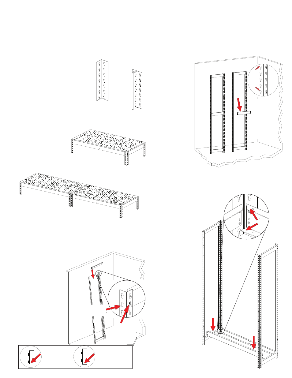
4.
Place a third front-to-back end support in the
middle keyholes of the two uprights
(or at whatever
level you want
your third shelf
to be). This
forms one
end of the
shelving unit.
5. Repeat steps
3 and 4 to
construct a
second set
of unit ends.
NOTE: If you
are planning to
install an adder unit,
this second set should consist of ZTP uprights
(Ref. No. 1b) to act as an intermediate assembly.
Carefully re-read through step 2 to better
understand this.
2.
Depending upon whether you
are assmebling a single unit or
an adder unit, you may have
one or both of the styles of
upright shown at right:
"T" Post
(ZTP)
B. Two or more units with High Capacity Posts
(SUR) on each end and "T" Posts (ZTP) as
intermediate posts.
1.
The reference numbers used throughout this sheet
refer to the illustration on the back cover. This is to
help you to identify the various
parts as they are mentioned.
LEFT-TO-RIGHT
SUPPORT (LRC) has
an added flange at the
bottom for strength.
A single unit uses SUR posts for all four uprights,
as shown below in Figure A. If you plan on
assembling mulpitle sections, however, you should
build your starter unit
with two ZTP posts
on one end, which
will provide common
posts for adjacent
sections, as shown
in Figure B.
FRONT-TO-BACK
SUPPORT (LRA)
has no flange at
the bottom.
6.
With the help of an
associate, connect
the two unit ends
with left-to-right
channel beams
(Ref. No. 3). If the
top flange on the
front-to-back end
support interferes
with the top flange
on the channel
beam, your
channel beam is
upside-down.
The flange with
the angled ends
must be on top,
as shown at right.
Be sure that the
channel beams
are fully seated,
as was illustrated
in step 3.
High Capacity
Post (SUR)
A. Single unit with four
High Capacity Posts (SUR).
3.
With help from an associate, or using a wall for
support, connect two SUR uprights (Ref. No. 1a)
together with two front-to-back supports (Ref. No.
2), one at the top and one near the bottom (you
should leave the bottom keyhole
slot empty). Be sure the
supports are fully
seated in the slots,
as shown at right.
NOTE: Front-to-
back supports are
different than left-
to-right supports.
Be sure you are
using the correct
supports on the
ends, as shown
in the box below.
ZTP
SUR
SUR
NOTE: Inset is
shown from
opposite side.
Supports are
properly seated
when alignment
hole is fully visible
Narrow area
of keyhole slot
is at bottom
Every 4th hole
is flattened at top
NOTE: Every
fourth keyhole
slot is shaped
differently (with
a flattened top)
for easier
alignment of
supports, as
shown above.
Proper orientation
of channel beam:
Flange with angled
end is on top;
Flange with flat
end is on bottom.
LRA
LRC