Handle/locking system installation instructions – Tennsco 1430 User Manual
Page 3
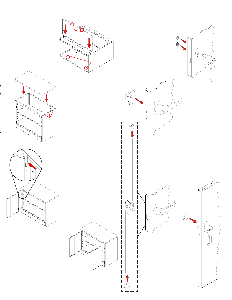
2.
Turn the handle to
the open position,
and place the
locking cam (Ref.
No. 13) over the
square shank of
the door handle.
The latch must be
facing downward
as shown.
Insert
shelf
into
bottom
lances.
13.
Attach the right door
Ref. No. 10) to the unit
in the same way you
attached the left door.
1.
Place the locking
handle (Ref. No. 12)
on the right hand
door and fasten with
two slotted bolts with
lockwashers.
Handle/Locking System Installation Instructions
4.
Place the locking cam
retainer (Ref. No. 14)
over the square
shank of the door
handle. Tap on the
edges of the cam
retainer with a
hammer until retainer
sits firmly against the
locking cam.
3.
With the handle still in the open
position, hook the locking bars (Ref.
No. 11) to the locking cam (see "A" at
left). Then, hold the lock bars in
position while sliding the nylon lock
bar guide inserts (Ref. No. 15) over
the lock bar ends and through
the door slots (see "B" at left).
A
B
14.
Instructions for attaching the
handle and locking mechanism
are given at right.
9.
Place the bottom (Ref. No. 7) in the bottom
lances of the shelf
adjustment strips.
The flange with two
holes should face the
front, and it should
hang over the sill.
Bolt to the sill with
two bolts and nuts.
10.
Stand the unit upright. Then,
attach the top (Ref. No. 8) by
lowering it straight down so
that the weld studs fit into
the three holes on each side.
Secure these six weld studs
with six nuts. Next, tighten
the top to the back panel
with three bolts and nuts.
12.
Attach the left door (Ref.
No. 9) to the unit by
placing the door on the
hinges, aligning the holes,
and using a hammer to tap
the hinge pins (Ref. No.
16) into place with the side
of a screwdriver.
Weld
studs fit
through
these
three
holes
B
Inset E
Two
holes
must
be
in front.