Assembly of 1430 cabinets – Tennsco 1430 User Manual
Page 2
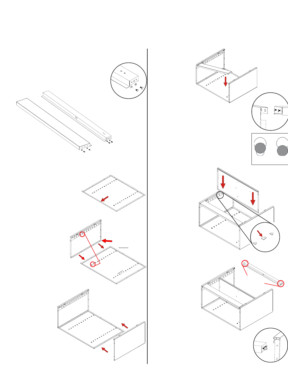
ASSEMBLY OF 1430 CABINETS
3.
Place the cabinet back (Ref. No. 1) on a protected
surface to prevent scratching the
paint. The flange on the bottom
of the back should be
facing upward.
5.
Attach the right side (Ref. No. 3) to the back in
the same manner as
you did in step 3.
Make sure
that the lances
on the right
side are
pointed in the
same direction as
those on the back and
the left side.
Flange
faces
upw
ard
7.
Insert a shelf (Ref. No. 4) near the
center of the cabinet. Do this by
inserting the shelf edges into the lances
on all four strips. Be
sure that the channeled
edge of the shelf is
toward the cabinet front.
If a lance is too
tight, it may be
helpful to use a
screwdriver to
SLIGHTLY pry it
open. (NOTE: The
shelf may be moved
moved to another level
later, if so desired.
Inset A
4.
Attach the left side (Ref. No.2 ) to the back by
placing flange (A) around the
back and bolting the
pieces together with
seven bolts and
nuts (Ref. Nos. 18
& 19). Be sure
that the lances on
all shelf adjustment
strips (B) point in the
same direction.
6.
Locate the two keyhole-
shaped slots on the
front of each end-
panel bottom.
Attach the sill
(Ref. No. 6) by
inserting the loose
bolt heads (which you
attached to the sill in step 2) into
the large end of the keyhole slots
(Inset B). Position by sliding the bolts
securely into the smaller end of the
slots. Inset C (below right) shows
improper and proper seating of bolt
heads. Tighten the four nuts securely.
Tools Needed: A free
11
/
32
" nut driver is provided with each Tennsco cabinet (Ref. No. 17). In addition,
you will need a flathead screwdriver. A hammer is required to install the hinge pin and lock bar.
Two people recommended for assembly. Approximate assembly time: 15 to 25 minutes.
Inset B
Inset C
Improperly
seated
Properly
seated
2.
Prepare the header (Ref. No. 5) for
installation by inserting a bolt into
the two outside holes on each end,
as shown in Inset A.
The center hole
should remain empty.
Loosely attach nuts to
each bolt, leaving
enough slack so
that the bolt
heads may
later be
inserted into a slot.
Prepare the sill (Ref. No. 6) in the same way.
1.
All reference numbers refer to the illustration on
the back cover. This is to help you to identify the
various parts as they are mentioned.
8.
Locate the two keyhole-shaped slots on the top front
of each end-panel. Attach the
header (Ref. No. 5) in the
same way you attached
the sill, by inserting
the previously
attached loose bolt
heads into the
large end of the
keyhole slots (Inset D).
Position by sliding the
bolts securely into the smaller
end of the slots. Refer to Inset C
(in step 6 above) for improper and
proper seating of the bolt heads.
Tighten the four nuts securely.
Shelf inserts
into tab.
Hea
der
Sill
A
Flange goes
under back
B
All
lances
point
UP
on
both
back
and
side.
Two bolts
and nuts on
each side
Inset D