Controller wiring diagram, Model # sp-8550 – SnowEx SP-8550 User Manual
Page 20
L1218 © Trynex International 2009
MAX — 20
Controller Wiring Diagram
Black
Negative (–)
Vibrator
Red Positive (+)
Vibrator
Black Negative (–)
Spinner
Red Positive (+)
Spinner
Black Negative (–)
MAIN INPUT
POWER
OUTPUT
Red
Positive (+)
Auger
Black Negative (–)
Auger
Red Positive (+)
20 Amp
Circuit Breaker
Pre-Wetting System
Output Data Port
20
Connect to control
mating half
Positive
White with Red Tracer (+) to battery
Ring Terminal
Negative
Black (–) to battery
Ring Terminal
* NOTE:
A) Leads must only be attached to battery.
B) 100 Amp breaker must be inserted.
D6837 Control Power Cable with D6840 Breaker
Key Part No. Description
Qty.
D 6837
Control Power Cable 1
D 6839
6 GA. Breaker Wire 1
D 6840
100 AMP Resetable Breaker 1
Model # SP-8550
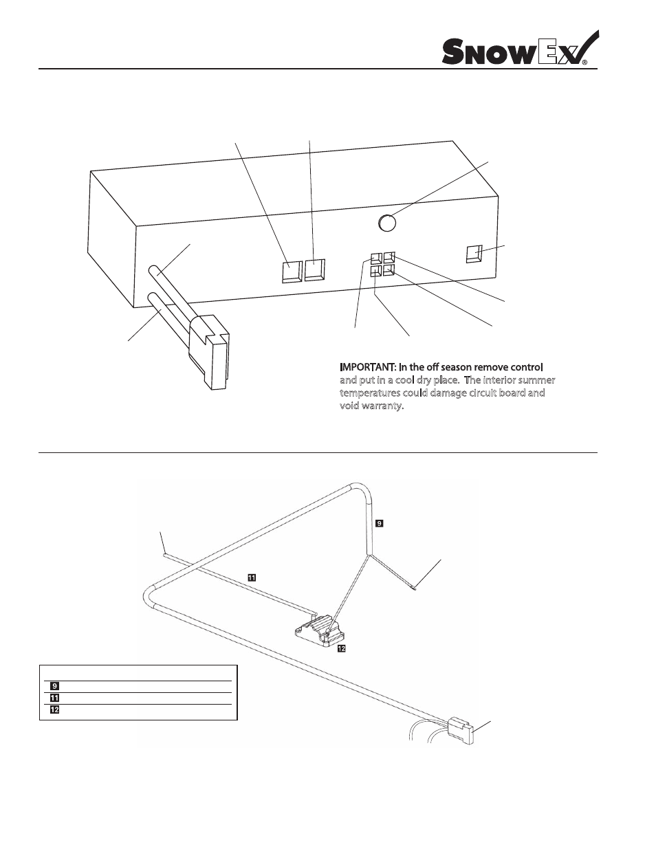
and put in a cool dry place. The interior summer
temperatures could damage circuit board and
void warranty.
Leads for Work Light
(-)
(+)
- SD-95 (24 pages)
- PWS-100 (40 pages)
- PPT-175 (1 page)
- PMT-175-C (3 pages)
- PMT-175 (3 pages)
- OFK-020 (2 pages)
- MGK-020 (2 pages)
- HRK-020 (8 pages)
- GAK-020 for SP-575 and SP-1075 (2 pages)
- DRM-175 (2 pages)
- ADF-020 For SP-575 and SP-1075 (2 pages)
- PWX-200 (28 pages)
- RHT-375 (2 pages)
- RHT-380 (12 pages)
- SD-600 Installation (12 pages)
- SD-600 Owners Manual (12 pages)
- TPR-020 (2 pages)
- SL-80 (28 pages)
- SP-100 (25 pages)
- SP-575X (28 pages)
- SP-725G (21 pages)
- SP-125 / US-100 (27 pages)
- SP-1575 (32 pages)
- SP-65 (24 pages)
- SP-3000 (31 pages)
- Bulk-Pro 1875 (51 pages)
- SP-2400 (35 pages)
- SP-2200 (36 pages)
- SP-7000 Assembly Instructions (12 pages)
- SP-7000 Owners Manual (16 pages)
- SP-7550 (36 pages)
- SP-85 (28 pages)
- SP-8500 (34 pages)
- SR-110 (28 pages)
- VBR-400 (12 pages)
- SP-9800X (40 pages)
- SP-9500X (40 pages)
- SP-9300X (40 pages)
- SP-9300 (40 pages)
- Wireless Spreader Key Fob Mating (1 page)
- SS-4000 (24 pages)
- SSH-175 (1 page)
- TLR-175 (1 page)
- TPM-175 (1 page)