Step 12 securing your cover, Step 11 installing auger anchors – ShelterLogic 58542 Run-In Shed 22 x 24 x 12 User Manual
Page 6
Step 12
Securing Your Cover
Pull the cover over the frame. The welded in webbing should be on the front and back of the building. Also note that
the pocket with the cutouts running along the sides of the cover should be on the inside and near the ground. Install
the "S" hooks from the ratchet assemblies into the legs of the shelter. Pull the webbing carefully to remove slack from
the cover. Be careful not to pull the webbing through the opposite side. Insert the webbing into the spindle of the ratchet
and pull tight. Wind the ratchet enough so that the webbing overlaps itself. Repeat the process of tightening one side
and then the other until the cover is as tight as possible and still even on the rib.
NOTE: The logos should be horizontal and about 5' above the ground on the outside of the garage.
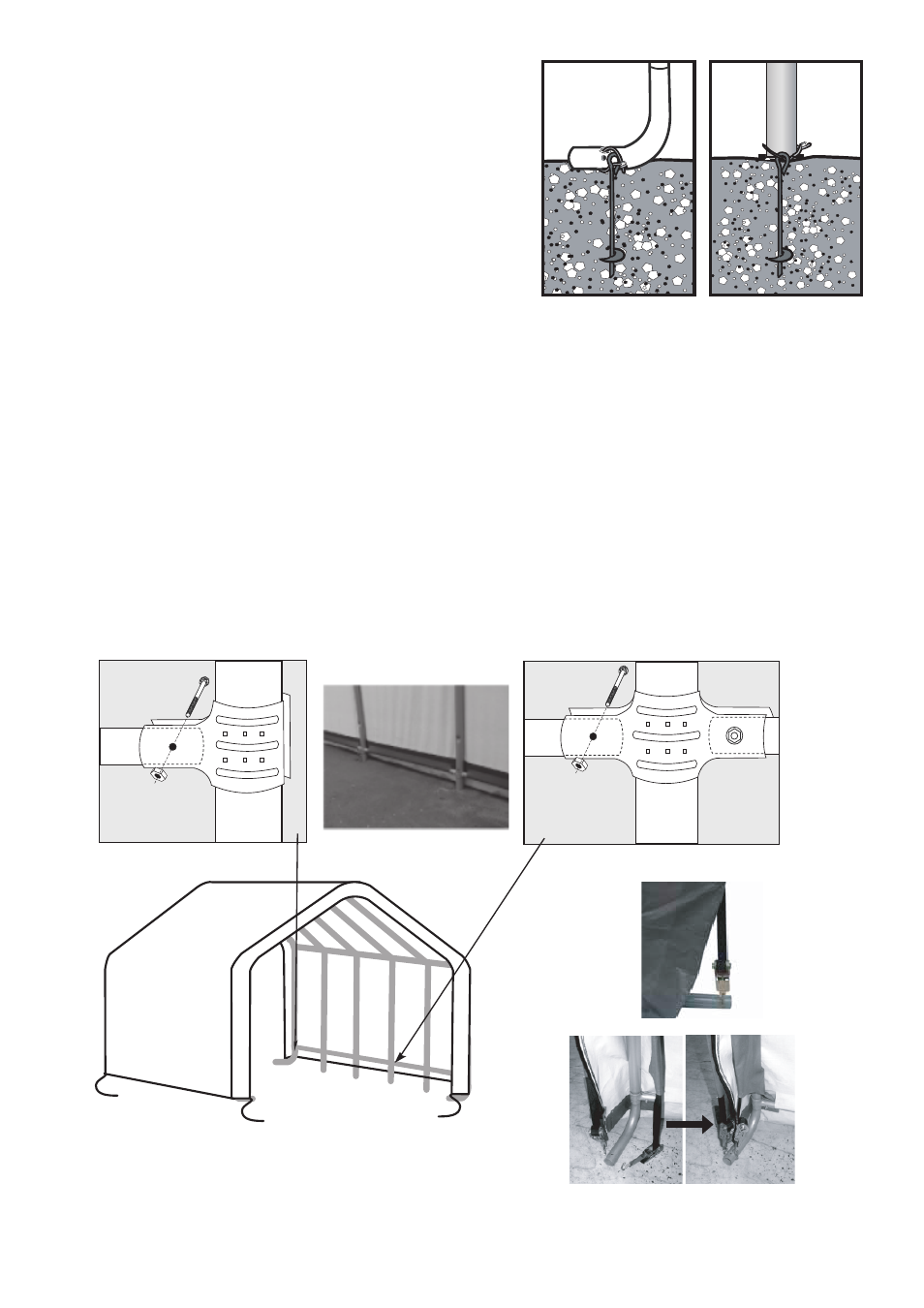
After the cover is tight end to end remove the 45" cover rails. Insert the cover rails into the pockets of the cover.
Re-clamp the rails to the ribs with the 3-way
(Fig.14)
and 4- way
(Fig.15)
clamps. Check that the rails are evenly
spaced above the ground on both sides.
(Fig.16)
Push down the connectors, one at a time, to tension the cover.
Tighten the bolts to hold tightly.
STEP 11 INSTALLING AUGER ANCHORS
Using a 3/4" pipe or steel rod, (a car tire iron works also) placed
through the eyelet on the auger, screw it into the ground. Start at
the four corners of the unit and space the remainder out evenly.
Be sure to screw the anchor in fully (the eyelet should be a level
where it can be securely attached to the frame. Wrap the cable
provided through the eyelet of the anchor and around the frame.
Secure the cable with the clamp(s) provided.
(Fig.13)
WARNING:
DO NOT INSTALL THE END PANELS OR COVER ON THE
SHELTER UNTIL IT HAS BEEN PROPERLY ANCHORED.
* The ratchets
should be checked
monthly to make sure
the cover is tight.
Outside Corner View
Fig. 16
Fig. 17
corner leg
clamps
11130
690
11106
Fig.14
middle leg
clamps
11130
11107
690
Fig.15
Fig.13
(Fig.17)
Page 6