Step 4 step 5 step 6 – ShelterLogic 58542 Run-In Shed 22 x 24 x 12 User Manual
Page 4
Page 4
STEP 4
STEP 5
STEP 6
middle leg
clamps
11107
11130
690
corner leg
clamps
11130
690
11106
11013
11016
11105
11106
11107
Wind Brace
11134 Bolt
11102
11013
11016
11102
11105
11106
11107
11019
11134 Bolt
11131 Bolt
11132 Bolt
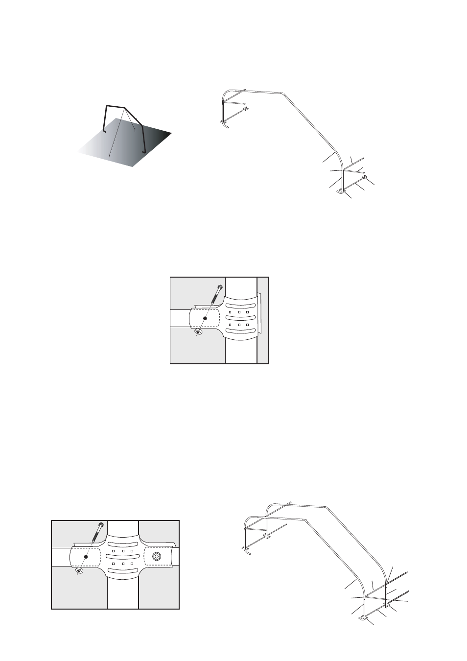
With help stand the first end rib vertically and lean against a permanent structure such as a tree or a fence
(Fig.5)
. Attach the
plain end of a #11102 horizontal tube and a wind brace assembly to the first rib using a #11134 5/16 X 4 1/2" bolt and
a #690 5/16" nut on the INSIDE of the bow, on each side bend just above the joint of the side bend/extension
(Fig.6)
. Repeat
the same steps on opposite side.
Place (2) #11106 3-Way Clamps around #11016 Bent Leg. Insert #11105 Cover Rail into the clamp and attach using a
#648 5/16 X 2" bolt and #690 5/16" nut. Position the clamp about five inches above the ground and tighten the nut
and bolt finger tight
(Fig.7)
. Repeat the same steps on opposite side.
With help position the first middle rib about four feet from the first end rib. While one person holds the middle rib vertical
the other person should raise the previously installed #11102 cross rail and place another #11102 over each of the previous.
Raise the two rails so they are horizontal and attach to the middle cross rail using a #11132 5/16 X 4" bolt and a #690
5/16" nut. Attach a #11107 4-Way Clamp to the end of the (2) cover rail tubes using a #648 5/16 X 2" bolt and a #690 5/16"
nut.
(Fig.8)
Place the clamp around the middle leg and insert a #11105 cover rail into the opposite side of the clamp and attach
with a #648 5/16 X 2" bolt and a #690 5/16" nut. Position the clamp about five inches above the ground and tighten
finger tight. Raise the cross brace to the middle rib and attach it to the rib using a #11131 5/16 X 2 3/4" bolt and a #690
5/16" nut,
(Fig.9)
Repeat these steps for the opposite side.
Repeat the cross rail installation for the remaining middle legs.
Fig.5
Fig.6
Fig.7
Fig.8
Fig.9