Step 7: secure base feet fig. 7, Step 8: install auger anchors fig. 8, Step 9: end panel installation fig. 9a, 9b & 9c – ShelterLogic 71534 Peak Style Storage Shelter 12 x 20 x 8 User Manual
Page 4
Page 5
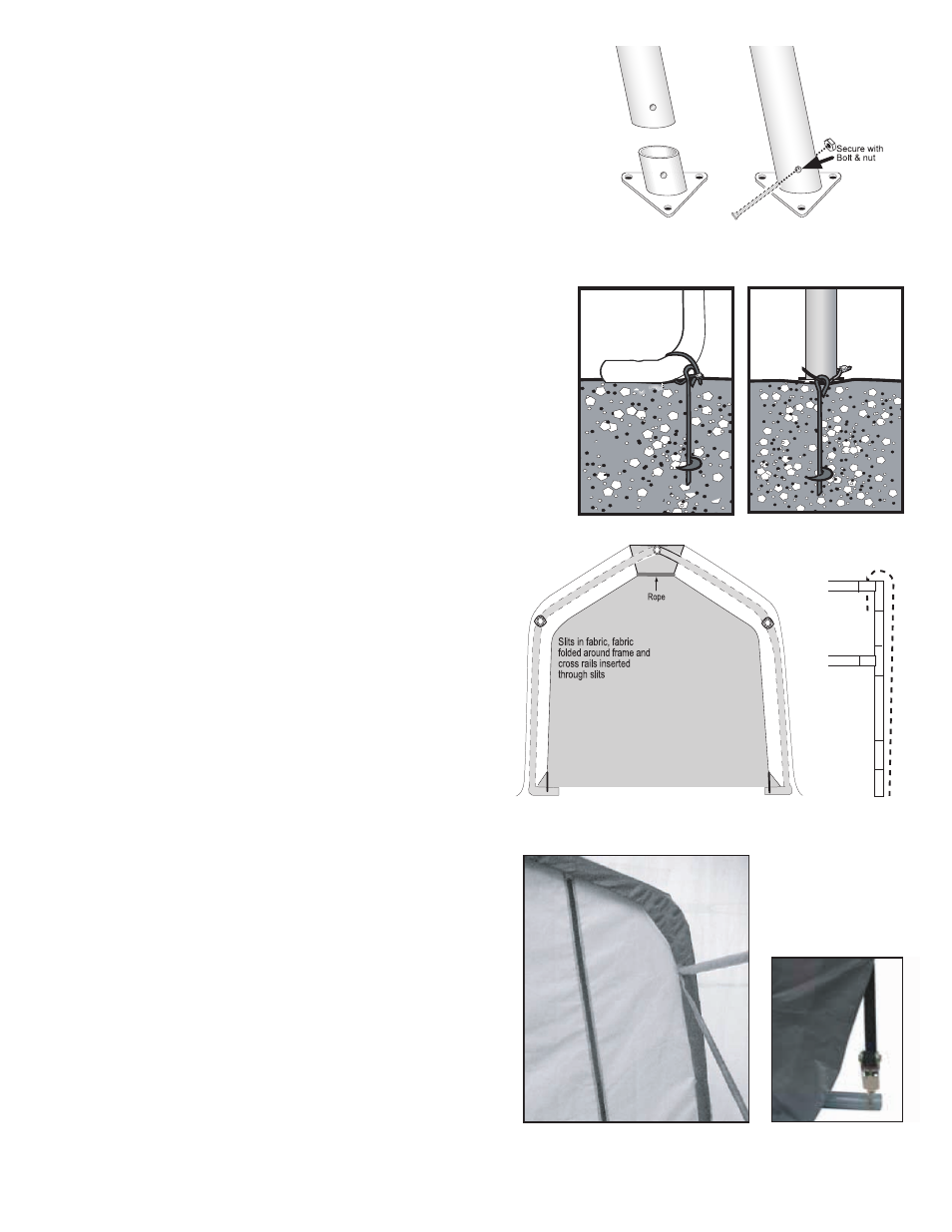
STEP 7: SECURE BASE FEET
Fig. 7
Fig. 7
STEP 8: INSTALL AUGER ANCHORS
Fig. 8
Fig. 8
Side View
Inside View
STEP 9: END PANEL INSTALLATION
Fig. 9A, 9B & 9C
Fig. 9A
Fig. 9B
Depending on the model you have purchased, your base feet will either
fit onto the outside of the leg pole or slide into the bottom of the leg pole.
After installing the base feet line up the holes in the leg to the holes in
the feet and secure with the hardware indicated in Fig. 7.
Using a ¾” pipe or steel rod (a car tire iron works also) placed
through the eyelet of the auger; screw the anchor into the ground.
Start at the corners of the shelter and space the remaining anchors
evenly along the length of the shelter. Screw the anchor into the
ground until the eyelet is sticking out of the ground by 1-2” so it can
be anchored to the legs. Wrap the cable provided through the
eyelet of the anchor and around the frame as indicated in Fig. 8.
Secure the cable with the clamp(s) provided.
Hold the end panel at the top center with the white inner
surface facing the inside of the shelter (if you have a
white shelter the inner surface has the visible weld seams).
Carefully remove the top rail from the top bend and place
the webbing in between the two. The top rail should pass
through the loop of the webbing. Replace the top rail onto
the top bend and secure it with the hardware indicated
in Fig. 9A, 9B.
Remove the nut from the side rail and carefully pull the
side rail away from the ShelterLock (the rail only needs to
be pulled away enough to pass the webbing through the
connection).
If this connection has the wind brace on it
remove the wind brace end before pulling the side rail.
When the webbing is through replace the side rail, and the
cross rail if necessary Fig 9C. Replace the nut and tighten.
Repeat this for the other side.
Locate where the webbing exits the pocket on each side of
the end panel. Pull the webbing carefully to remove the slack
from the end panel. Be careful not to pull the webbing through
the other side of the panel. Install the “S”-hook from the
ratchet into the leg of the shelter Fig 9D. Insert the webbing
into the spindle of the ratchet and pull tight. Wind the ratchet
enough so that the webbing overlaps itself. Repeat the
process on the other side of the panel. Position the end panel
so that it is centered on the building. Tighten the ratchets,
alternating from one side to the other, until the end panel is
tight. Repeat these steps on the other end of the building.
Fig. 9C
Fig. 9D