Pilot valve, Pilot valve actuator, Trouble shooting – SANDPIPER MSA25 User Manual
Page 8: Safety warning
msa1dl4sm-rev0711
Model MSA1, MSA25 Type 4 Page 7
Remove the spool from the sleeve. Using an arbor press or bench vise (with
an improvised mandrel), press the sleeve from the valve body. Take care not to
damage the sleeve. At this point, inspect the o-rings on the sleeve for nicks, tears or
abrasions. Damage of this sort could happen during assembly or servicing. A sheared
or cut o-ring can allow the pump’s compressed air supply to leak or bypass within the
air valve assembly, causing the pump to leak compressed air from the pump air exhaust
or not cycle properly. This is most noticeable at pump dead head or high discharge
pressure conditions. Replace any of these o-rings as required or set up a routine,
preventive maintenance schedule to do so on a regular basis. This practice should
include cleaning the spool and sleeve components with a safety solvent or equivalent,
inspecting for signs of wear or damage, and replacing worn components.
To re-install the sleeve and spool set, lightly lubricate the o-rings on the sleeve
with an o-ring assembly lubricant or lightweight oil (such as 10 wt. air line lubricant).
Re-install one end cap, and retaining ring (see safety warning) on the valve body.
Using the arbor press or bench vise that was used in disassembly, carefully press the
sleeve back into the valve body, without shearing the o-rings. You may have to clean
the surfaces of the valve body where the end caps mount. Material may remain from
the old gasket. Old material not cleaned from this area may cause air leakage after
reassembly. Take care that the bumper stays in place allowing the sleeve to press in all
the way. Reinstall the spool, opposite end cap and retaining ring (see safety warning)
on the valve body. After inspecting and cleaning the gasket surfaces on the valve body
and intermediate, reinstall the valve body on the pump using new gaskets. Tighten the
four hex head capscrews evenly and in an alternating cross pattern.
PILOT VALVE
The pilot valve assembly is accessed by removing the main air distribution valve
body from the pump and lifting the pilot valve body out of the intermediate housing.
Most problems with the pilot valve can be corrected by replacing the o-rings. Always
grease the spool prior to inserting it into the sleeve. If the sleeve is removed from
the body, reinsertion must be at the chamfered side. Grease the o-rings to slide the
sleeve into the valve body. Securely insert the retaining ring around the sleeve. When
reinserting the pilot valve, push both plungers (located inside the intermediate bracket)
out of the path of the pilot valve spool ends to avoid damage.
PILOT VALVE ACTUATOR
Bushings for the pilot valve actuators are held in the inner chambers with retain-
ing rings. An o-ring is behind each bushing. If the plunger has any sideways motion,
check o-rings and bushings for deterioration/wear. The plunger may be removed
for inspection or replacement. First remove the air distribution valve body and the
pilot valve body from the pump. The plungers can be located by looking into the
intermediate. It may be necessary to use a fine piece of wire to pull them out.
The bushing can be turned out through the inner chamber by removing the outer
chamber assembly. Replace the bushings if pins have bent.
TROUBLE SHOOTING
1. Pump will not cycle
A. Check to make sure the unit has enough pressure to operate and that the air inlet
valve is open.
B. Check the discharge line to insure that the discharge line is neither closed nor
blocked.
C. It the spool in the air distribution valve is not shifting, check the main spool. It must
slide freely.
D. Excessive air leakage in the pump can prevent cycling. This condition will be
evident. Air leakage into the discharge line indicates a ruptured diaphragm. Air
leakage from the exhaust port indicates leakage in the air distribution valve. See further
service instructions.
E. Blockage in the liquid chamber can impede movement of diaphragm.
2. Pump cycles but will not pump
A. Suction side of pump pulling in air. Check the suction line for air leaks and be sure
that the end of the suction line is submerged. Check flange bolting. Check valve flanges
and manifold to chamber flange joints.
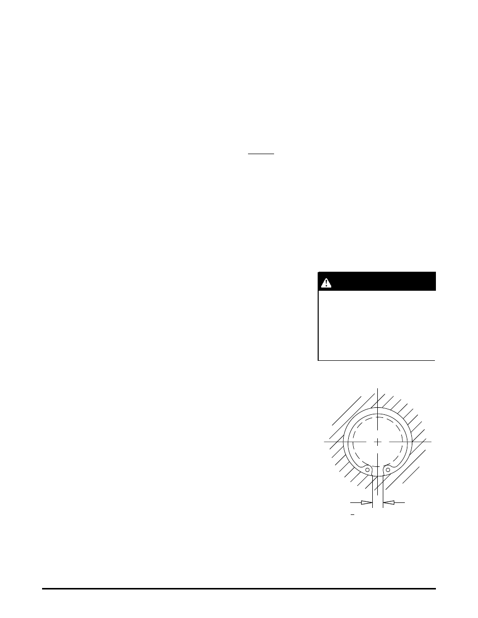
SAFETY WARNING
To assure proper pump func-
tion and safe installation of the
retaining ring, check the gap “G”
dimension for full installation
into the valve body grooves.
> .232 "G"
Dimensions between lugs