Air supply – SANDPIPER SET2-A User Manual
Page 2
Page 2 Model SET2-A Type 3
520-117-000 5/99
2. Remove the entire discharge manifold assembly exposing the ports in the outer
diaphragm chambers.
3. With 5-10 PSI of air pressure at inlet, lock the spool to one side with locking pin (safety
clip; item 61). You will fill the opposite side diaphragm from the “Locked Area.”
4. Fill with 2500MI. (84.53 fl. oz.) by volume with the driver liquid. It is imperative that
the driver liquid chambers be filled with the correct amount of driver liquid as too
little or too much will cause premature diaphragm failure and erratic pumping.
5. After filling with the proper amount of liquid, if the liquid does not come to the top of
the fill hole, pressure should be applied to the Teflon diaphragm with a blunt tool
through the material flow port in the outer chamber until it does come to the top.
Relieving air pressure will relax diaphragms at this point.
6. When the driver fluid rises to the top of the fill plug hole, screw the boss plug, with
o-ring installed, into the chamber. (Do not overtighten.) Remember to keep pressure
on the Teflon diaphragm until the boss plug is tight to prevent air from drawing back
into the chamber.
7. Filling the opposite side is accomplished in the same manner as described.
Air SUPPLY
Do not connect the unit to an air supply in excess of 125 PSI (8.61 bars). Install
a shutoff valve in the air supply line to permit removal of the unit for servicing. When
connecting an air supply of rigid piping, mount a section of flexible line to the pump to
eliminate piping strain. In permanent installations, an air line filter is recommended.
A NOTE ABOUT Air VALVE LUBricATiON
The SandPiPer pump’s pilot valve and main air valve assemblies are designed to
operate WITHOUT lubrication. This is the preferred mode of operation. There may be
instances of personal preference, or poor quality air supplies when lubrication of the
compressed air supply is required. The pump air system will operate with properly lubricated
compressed air supplies. Proper lubrication of the compressed air supply would entail
the use of an air line lubricator (available from Warren Rupp) set to deliver one drop of
10 wt., non-detergent oil for every 20 SCFM of air the pump consumed at its point of
operation. Consult the pump’s published Performance Curve to determine this.
It is important to remember to inspect the sleeve and spool set routinely. It should
move back and forth freely. This is most important when the air supply is lubricated. If a
lubricator is used, oil accumulation will, over time, collect any debris from the compressed
air. This can prevent the pump from operating properly.
Water in the compressed air supply can create problems such as icing or freezing of
the exhaust air causing the pump to cycle erratically, or stop operating. This can be
addressed by using a point of use air dryer to supplement a plant’s air drying equipment.
This device will remove excess water from the compressed air supply and alleviate the
icing or freezing problem.
ESADS: EXTErNALLY SErVicEABLE Air
DiSTriBUTiON SYSTEM
Please refer to the exploded view drawing and parts list in the Service Manual
supplied with your pump. If you need replacement or additional copies, contact your
local Warren Rupp Distributor, or the Warren Rupp factory Literature Department at the
number shown below. To receive the correct manual, you must specify the MODEL and
TYPE in formation found on the name plate of the pump.
MODELS WiTH 1" SUcTiON/DiScHArGE Or LArGEr, AND
METAL cENTEr SEcTiONS
The main air valve sleeve and spool set is located in the valve body mounted on the
pump with four hex head capscrews. The valve body assembly is removed from the pump
by removing these four hex head capscrews.
With the valve body assembly off the pump, access to the sleeve and spool set is
made by removing four hex head capscrews (each end) on the end caps of the valve
body assembly. With the end caps removed, slide the spool back and forth in the sleeve.
The spool is closely sized to the sleeve and must move freely to allow for proper pump
operation. An accumulation of oil, dirt or other contaminants from the pump’s air supply,
or from a failed diaphragm, may prevent the spool from moving freely. This can cause
the spool to stick in a position that prevents the pump from operating. If this is the case,
the sleeve and spool set should be removed from the valve body for cleaning and
further inspection.
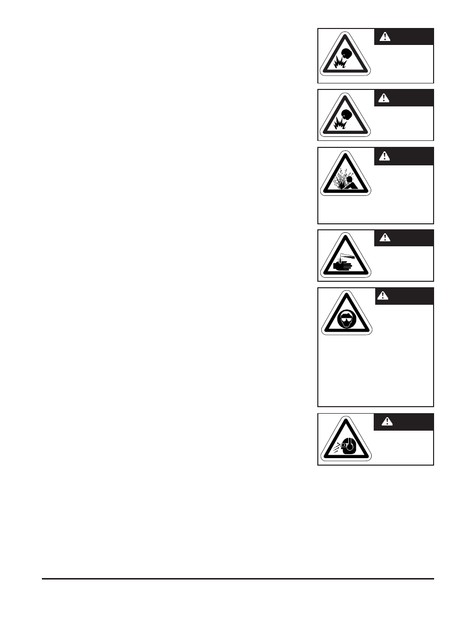
Do not smoke near
t h e p u m p o r u s e
the pump near an
open flame. Fire or
explosion could result.
WArNiNG
This pump must not be
used for fluid transfer
into aircraft.
WArNiNG
T h i s p u m p i s
pressurized internally
with air pressure
during operation.
Always make certain
that all bolting is in good condition and
that all of the correct bolting is reinstalled
during assembly.
WArNiNG
When used for toxic or
aggressive fluids, the
pump should always
be flushed clean prior
to disassembly.
WArNiNG
Before doing any
main-tenance on the
pump, be certain all
pressure is completely
v e n t e d f r o m t h e
pump, suction, discharge, piping, and
all other openings and connections. Be
certain the air supply is locked out or
made non-operational, so that it cannot
be started while work is being done on
the pump. Be certain that approved eye
protection and protective clothing are
worn all times in the vicinity of the pump.
Failure to follow these recommendations
may result in serious injury or death.
WArNiNG
Airborne particles and
loud noise hazards.
Wear ear and eye
protection.
WArNiNG