SANDPIPER PB 1/4 User Manual
Page 7
pb025nmdl3sm-rev0614
Page 5
PRINCIPLE OF PUMP OPERATION
This ball type check valve pump is
powered by compressed air and is a
1:1 ratio design. The inner side of one
diaphragm chamber is alternately
pressurized while simultaneously
exhausting the other inner chamber.
This causes the diaphragms, which are
connected by a common rod secured by
plates to the centres of the diaphragms,
to move in a reciprocating action. (As
one diaphragm performs the discharge
stroke the other diaphragm is pulled
to perform the suction stroke in the
opposite chamber.) Air pressure is
applied over the entire inner surface
of the diaphragm while liquid is dis-
charged from the opposite side of the
diaphragm. The diaphragm operates in a
balanced condition during the discharge
stroke which allows the pump to be
operated at discharge heads over 200 feet
(61 meters) of water.
For maximum diaphragm life, keep the
pump as close to the liquid being pumped
as possible. Positive suction head in
excess of 10 feet of liquid (3.048 meters)
may require a back pressure regulating
device to maximize diaphragm life.
Alternate pressurizing and exhausting
of the diaphragm chamber is performed
by an externally mounted, pilot operated,
four way spool type air distribution valve.
When the spool shifts to one end of the
valve body, inlet pressure is applied to
one diaphragm chamber and the other
diaphragm chamber exhausts. When the
spool shifts to the opposite end of the
valve body, the pressure to the chambers
is reversed. The air distribution valve
spool is moved by a internal pilot valve
which alternately pressurizes one end
of the air distribution valve spool while
exhausting the other end. The pilot
valve is shifted at each end of the dia-
phragm stroke when a actuator plunger is
contacted by the diaphragm plate. This
actuator plunger then pushes the end
of the pilot valve spool into position to
activate the air distribution valve.
The chambers are connected
with manifolds with a suction and
discharge check valve for each chamber,
maintaining flow in one direction through
the pump.
INSTALLATION AND START-UP
Locate the pump as close to the
product being pumped as possible. Keep
the suction line length and number of
fittings to a minimum. Do not reduce the
suction line diameter.
For installations of rigid piping, short
sections of flexible hose should be
installed between the pump and the
piping. The flexible hose reduces
vibration and strain to the pumping
system. A surge suppressor is
recommended to further reduce
pulsation in flow.
AIR SUPPLY
Air supply pressure cannot exceed
100 psi (7 bar). Connect the pump
air inlet to an air supply of sufficient
capacity and pressure required for
desired performance. When the air
supply line is solid piping, use a short
length of flexible hose not less than 1/2"
(13mm) in diameter between the pump
and the piping to reduce strain to the
piping. The weight of the air supply line,
regulators and filters must be supported by
some means other than the air inlet cap.
Failure to provide support for the piping
may result in damage to the pump. A pres-
sure regulating valve should be installed
to insure air supply pressure does not
exceed recommended limits.
AIR VALVE LUBRICATION
The air distribution valve and the
pilot valve are designed to operate
WITHOUT lubrication. This is the pre-
ferred mode of operation. There may be
instances of personal preference or poor
quality air supplies when lubrication of
the compressed air supply is required.
The pump air system will operate with
properly lubricated compressed air supply.
Proper lubrication requires the use of an
air line lubricator (available from Warren
Rupp) set to deliver one drop of SAE
10 non-detergent oil for every 20 SCFM
(9.4 liters/sec.) of air the pump consumes
at the point of operation. Consult the
pump’s published Performance Curve to
determine this.
AIR LINE MOISTURE
Water in the compressed air supply
can create problems such as icing or
freezing of the exhaust air, causing the
pump to cycle erratically or stop operating.
Water in the air supply can be reduced
by using a point-of-use air dryer to
supplement the user ’s air drying
equipment. This device removes water
from the compressed air supply and
alleviates the icing or freezing problems.
AIR INLET AND PRIMING
To start the pump, open the air valve
approximately ½ to ¾ turn. After the pump
primes, the air valve can be opened to
increase air flow as desired. If opening
the valve increases cycling rate, but does
not increase the rate of flow, cavitation
has occurred. The valve should be closed
slightly to obtain the most efficient air flow
to pump flow ratio.
BETWEEN USES
When the pump is used for materials
that tend to settle out or solidify when not
in motion, the pump should be flushed
after each use to prevent damage.
(Product remaining in the pump be-
tween uses could dry out or settle out.
This could cause problems with the
diaphragms and check valves at restart.)
In freezing temperatures the pump must
be completely drained between uses in
all cases.
Figure 1
Figure 2
Figure 3
CHECK VALVE SERVICING
Need for inspection or service is
usually indicated by poor priming,
unstable cycling, reduced performance
or the pump's cycling but not pumping.
Remove the sixteen machine screws
securing the manifold assemblies to the
outer chambers. Inspect the surfaces
of both check valve and seat for wear
or damage that could prevent proper
sealing. If pump is to prime properly,
valves must seat air tight.
DIAPHRAGM SERVICING
Remove the two V-Band clamps
securing the outer chambers to the
intermediate housing. Remove the
diaphragm assembly (outer plate,
diaphragm, inner plate) by turning the
assembly counterclockwise using a 1/2"
(1.27 cm) wrench on the outer plate
lugs. (If a socket is used, it must be a six
point socket.) The interior components
consisting of the shaft seal and pilot
valve assembly are now accessible for
service.
Procedures for reassembling the
diaphragms are the reverse of the above.
Install the diaphragm with the natural
bulge outward.
Install the outer diaphragm plate on
the outside of the diaphragm and make
certain that the large radius side of the
inner plate is toward the diaphragm.
Tighten the outer diaphragm plate to
approximately 30 in./lbs. (3.39 Newton
meters).
Torque while allowing the diaphragm
to turn freely with plates. Use a wrench
on the outer diaphragm plate of the
Figure 4
opposite side to keep rod from rotating. If
the opposite chamber is assembled, the
rod need not be held.
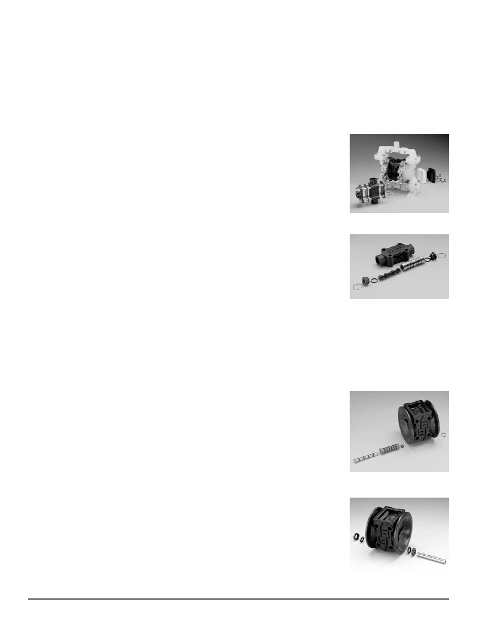
EXTERNALLY SERVICEABLE MAIN AIR
DISTRIBUTION VALVE
To service the main air distribution,
first shut-off and disconnect the air supply
to the pump. Remove the four long hex cap
screws and hex nuts (on opposite side of
pump) which fasten the main air valve
body (item 1), gaskets (item 8 and 11),
muffler (item 14), and caps (item 6 and
15) to the pump.
Once the main air valve body is off the
pump remove the retaining rings (items 7)
that hold the end caps in place. Remove
the end caps (items 6) to inspect the spool
and sleeve. Remove the main air spool
(part of item 2) and inspect for damage or
wear. Inspect the inside diameter of the
main air valve (item 2) for dirt, scratches,
or other contaminants. Remove and
replace the sleeve if needed. When
reinstalling the sleeve, apply a light
coating of grease to the six o-rings
(item 3) before inserting the sleeve into
the main air valve body. Align the holes
in the sleeve with the slots in main
valve body, making sure the sleeve is
centered in the bore. Clean the main
air valve spool, lightly grease the o-
rings, and insert into the sleeve flush
to one end. Reinstall the end caps and
retaining rings. The main air valve body
is now ready to put back on the pump.
Assemble the air inlet cap (item 9),
valve body gasket (item 8), to the main
air valve body (making sure the five rect-
angular slots face the air inlet cap), and
the intermediate gasket onto the four hex
capscrews and install onto the pump. Slide
the muffler (item 14) and the exhaust cap
(item 15) over the capscrews. Re-install
the washers (item 10) and hex nuts (items
16) onto the four hex capscrews and
torque to 30 in/lbs. (3.39 Newton meters).
SERVICING THE PILOT VALVE
To remove the pilot valve spool (item
23) first remove the end o-ring (item 24)
from one end of spool. Slide the spool
out of the sleeve and inspect the five
remaining o-rings (items 24) for damage
or wear. If necessary, replace damaged
o-rings. Inspect the inner diameter of pilot
valve sleeve (item 20) for scratches, dirt,
or other contaminants. Replace the sleeve
if necessary. To remove the sleeve first
remove the retaining ring from one end.
When installing a pilot valve sleeve first
lightly grease the six o-rings (items 21).
Insert the sleeve into the chamfered end
of bore on the intermediate bracket (item
13). Push the sleeve in until the shoulder
is flush to intermediate bracket surface
and install the retaining ring (item 22).
To install the pilot valve spool first lightly
grease the four interior o-rings and insert
into the pilot valve sleeve. After insert-
ing the spool into the sleeve install the
remaining loose o-rings onto spool.
SERVICING DIAPHRAGM ROD SEALS
To service the rod seals (item 18)
first remove pilot valve, then remove
the inserts on each of the intermediate
brackets (item 17) by prying them
out with a small flat screwdriver. After
removing the inserts take the K-R rod
seals out of the inserts and replace.
When reinstalling the seals, make sure
the open side of the seals face into the
counterbore in the inserts. To install the
inserts into intermediate bracket, simply
press the insert into the counterbore in
each of the intermediate bracket, making
sure that the closed side of insert faces out.
The inserts should be flush to the surface
of the intermediate bracket or slightly
below the surface when fully installed.