Solenoid shifted air valve, Optional – SANDPIPER S15 Metallic User Manual
Page 22
s15mdl1sm-rev0614
sandpiperpump
.
com
19
• Model S15 Metallic
Solenoid Shifted Air Valve
*Special Conditions For Safe Use
A fuse corresponding to its rated current (max. 3*I
rat
according IEC 60127-2-1) or a
motor protecting switch with short-circuit and thermal instantaneous tripping (set to rated
current) shall be connected in series to each solenoid as short circuit protection. For
very low rated currents of the solenoid the fuse of lowest current value according to
the indicated IEC standard will be sufficient. The fuse may be accommodated in the
associated supply unit or shall be separately arranged. The rated voltage to the fuse shall
be equal to or greater than the stated rated voltage of the magnet coil. The breakage
capacity of the fuse-link shall be as high as or higher than the maximum expected short
circuit current at the location of the installation (usually 1500 A). A maximum permissible
ripple of 20% is valid for all magnets of direct-current design.
Solenoid Shifted Air
Distribution Valve Option
Warren Rupp’s solenoid shifted, air distribution valve option utilizes electrical
signals to precisely control your SANDPIPER’s speed. The solenoid coil is
connected to a customer - supplied control. Compressed air provides the pumping
power, while electrical signals control pump speed (pumping rate).
Operation
The Solenoid Shifted SANDPIPER has a solenoid operated, air distribution valve
in place of the standard SANDPIPER’s pilot operated, air distribution valve.
Where a pilot valve is normally utilized to cycle the pump’s air distribution valve,
an electric solenoid is utilized. As the solenoid is powered, one of the pump’s air
chambers is pressurized while the other chamber is exhausted. When electric
power is turned off, the solenoid shifts and the pressurized chamber is exhausted
while the other chamber is pressurized. By alternately applying and removing
power to the solenoid, the pump cycles much like a standard SANDPIPER
pump, with one exception. This option provides a way to precisely control and
monitor pump speed.
Before Installation
Before wiring the solenoid, make certain it is compatible with your system voltage.
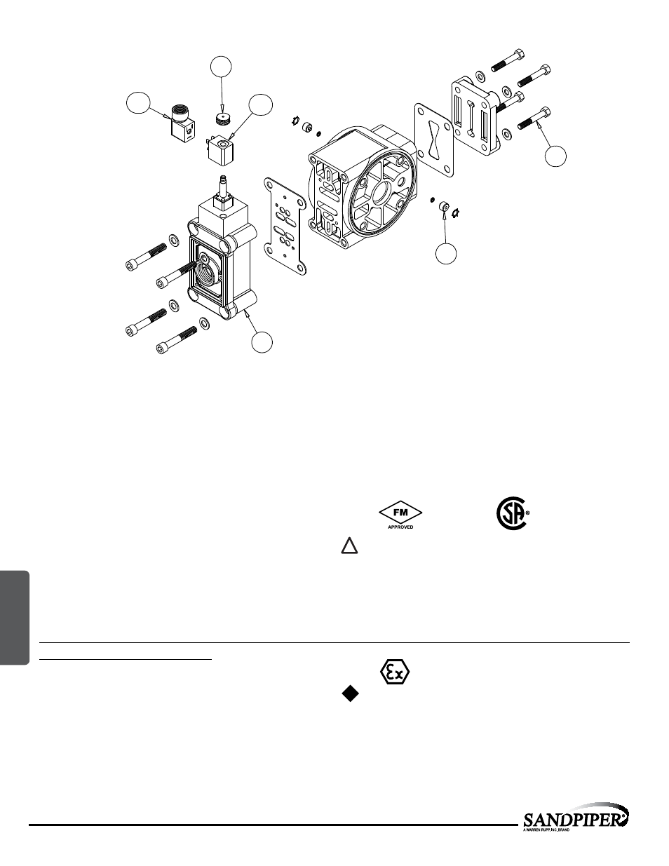
40
38
39
38
42
41
SOLENOID SHIFTED AIR VALVE PARTS LIST
(Includes all items used on Composite Repair Parts List except as shown)
Item Part Number Description
Qty
38
893-097-000
Solenoid Valve, NEMA4
1
39
219-001-000
Solenoid Coil, 24VDC
1
219-004-000
Solenoid Coil, 24VAC/12VDC
1
219-002-000
Solenoid Coil, 120VAC
1
219-003-000
Solenoid Coil, 240VAC
1
40
241-001-000
Connector, conduit
1
241-003-000
Conduit Connector with
1
Suppression Diode (DC Only)
41
170-029-330
Capscrew, Hex HD 5/16-18 x 1.50
4
42
618-051-150
Plug
2
IEC EEX m T4
For Explosion Proof Solenoid Coils used in North America and
outside the European Union.
39
219-009-001 Solenoid Coil, 120VAC 60 H
z
1
219-009-002 Solenoid Coil, 240VAC 60 H
z
1
219-009-003 Solenoid Coil, 12VDC
1
219-009-004 Solenoid Coil, 24VDC
1
219-009-005 Solenoid Coil, 110VAC 50 H
z
1
219-009-006 Solenoid Coil, 230VAC 50 H
z
1
Note: Item 40 (Conduit Connector) is not required
II 2G EEx m c T5
II 2D c IP65 T100°C
For ATEX Compliant Solenoid Coils used in the European Union
39
219-011-001
Solenoid Coil, Single mounting 12 VDC, 3.3W / 267mA
1
219-011-002
Solenoid Coil, Single mounting 24 VDC, 3.3W / 136mA
1
219-011-003
Solenoid Coil, Single mounting 110/120 VAC, 3.4W / 29mA
1
219-011-004
Solenoid Coil, Single mounting 220/240 VAC, 3.4W / 15mA
1
Note: Item 35 (Conduit Connector) is not required
*
II 2G EE
x
m
c
II T5
II 3/2 G E
x
m
c
II T5
II 2D
c
IP65 T100°c
Compressed Air Temperature Range: Maximum Ambient Temperature
to plus 50°C
6: OPTIONAL