Assembly, Tools required for assembly – RIKON Power Tools 70-425 User Manual
Page 7
Tools Required for Assembly
3.3 Stand Assembly
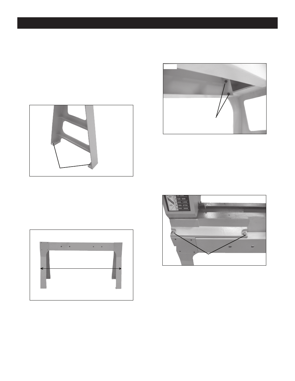
1. Remove the two stand legs from the carton and position
them approximately 54” apart (Fig.2) measuring from the
outside edges. Be sure that the shelves are facing inward and
that the double flared leg is on the left.
Fig.02
54”
Mounting Bolts
Fig.03
Fig.04
Mounting Bolts
CAUTION
To avoid injury, assistance required during assembly.
Note: The machine must not be plugged in and the power switch
must be in the OFF position until assembly is complete.
3.2 Determine Lathe Location in Workshop
1. Find a location in the workshop that is level and has adequate
lighting. Make sure that there is plenty of room between the lathe
and other machines. Place the lathe in an area that will support
its weight and is close to a power source.
Leveling Feet
Fig.01
3.4 Bolting Lathe to Stand
1. Lift lathe body by the bed only, not by the head stock or tail
stock assemblies.
2. Gently place the lathe body onto the stand and secure by using
six M10X40 hex bolts, six M10 flat washers, and six M10 locking
washers. (Fig.04)
Assembly
7
2.With assistance, lift stand body and carefully position the
stand legs to align the bolt holes. Secure stand to legs by
using eight M10X30 hex bolts and eight M10 flat washers.
(Fig.03)