Adjustments – RIKON Power Tools 10-346 User Manual
Page 14
14
Figure 18
Figure 19
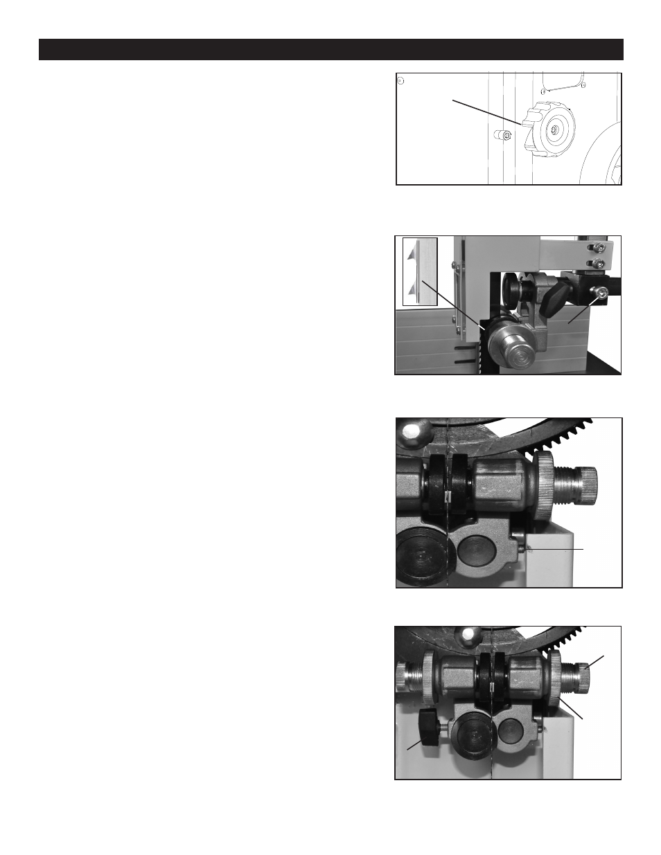
Figure 20
Figure 17
A
C
B
A
ADJUSTING THE BLADE GUIDES
Upper Guides: To adjust the upper blade guides,
first position the roller guides relative to the blade by
loosening the Allen cap head screw (A-Fig.18) and
sliding the guide assembly until the side roller guides
are approximately 1/16” behind the gullet of the blade,
then re-tighten the Allen cap head screw (A-Fig.18).
Next, set the roller guides to within 1/32” of the blade by
releasing the lock knob (B-Fig.18) and turning the micro-
adjusting knob (C-Fig.18). Do not set the guides too
close, as this will adversely affect the life of the blade.
When the correct adjustment is reached, lock the guides
in position by tightening the lock knob (B-Fig.18). Finally,
follow the same steps above to position the rear thrust
guide.
Lower Guides: To adjust the lower blade guides,
first loosen the hex nut (A-Fig.19) by placing a wrench
through acess hole in side of frame. Move the lower
guide support assembly to allow the side roller guides
to be approximately 1/16” behind the gullets of the
blade, and re-tighten the hex nut. Next set the roller
guides to within 1/32” of the blade by releasing the lock
knob (A-Fig.20) and turning the micro-adjusting knob
(B-Fig.20). Do not set the guides too close, as this will
adversely affect the life of the blade.
B
A
ADJUSTMENTS
Continued from Page 13
f) Re-tension the new blade by moving the quick
release lever (Fig.15) left to right and check the
blade tracking. With your hand, slowly spin the
upper wheel clockwise three times. The blade
should run in the center of both wheels. Refer to
“Tracking the Saw Blade” on page 12 for more
details.
g) Set the blade guides as described in the section
“Adjusting the Blade Guides” below on this page.
h) Close the hinged door on the blade guard
and tighten the wing screw (A-Fig.16).
i) Close and lock both the wheel doors (A-Fig.17)
before reconnecting the power supply.
1/16”
图13
A
C