Assembly – RIKON Power Tools 10-346 User Manual
Page 10
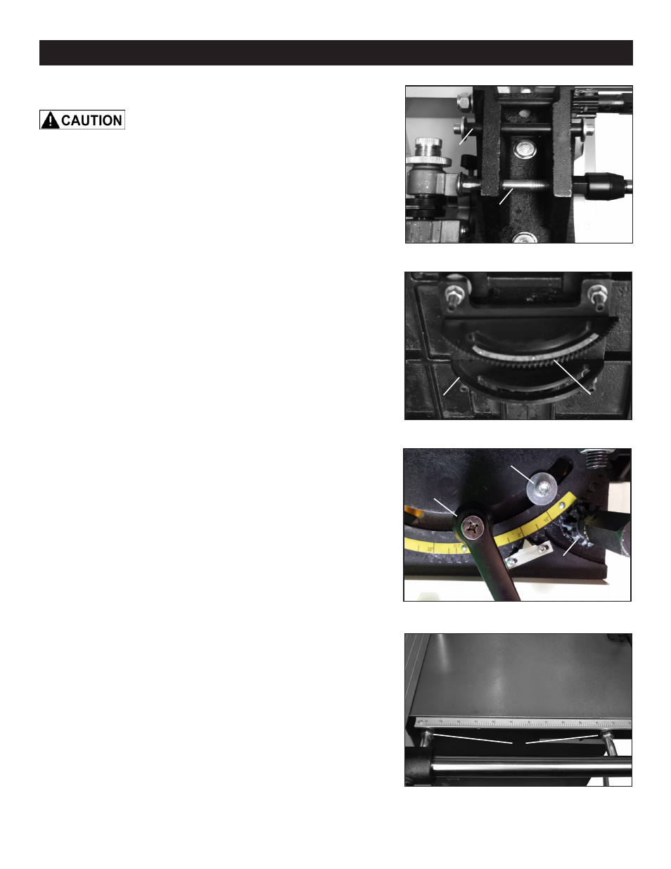
Figure 1
10
Figure 2
INSTALLING THE WORK TABLE
The Work Table is extremely heavy.
It may require two other individuals to assist with the
installation.
NOTE: The upper and lower bandwheel doors must
remain closed during table installation.
The guide shaft (A-Fig.1) and table locking hardware
(B-Fig.1) were installed on the lower trunnion (C-Fig.1)
during saw assembly. These need to be removed prior
to table installation.
NOTE: The bandsaw blade is installed at the factory. It
is recommended to remove the blade prior to installing
the table. See “CHANGING THE SAW BLADE” on page
13.
With the guide shaft, table locking hardware and blade
removed carefully lift the table (team lift) and lower the
upper trunnion (installed at factory) (A-Fig.2) onto the
lower trunnion. Ensure that the gear teeth on the upper
trunnion (B-Fig.2) engage the gear on the lower trunnion
(A-Fig.3).
Install the guide shaft and table locking hardware from
the left side of the upper trunnion (user cutting position)
through the lower trunnion and out the right side of the
upper trunnion.
NOTE: The table locking handle (B-Fig.3) is to be
installed on the right side of the upper trunnion in the
lower hole below the guide shaft position (C-Fig.3)
RIP FENCE RAIL
The Rip Fence Rail has been pre-assembled to the
work table for shipping. After mounting the work table
to the trunnions (see above instructions), the rail should
be checked to ensure that it is still properly tightened
in place to the table. If adjustments are needed, loosen
and/or re-tighten the four hex nuts on the fence bar
support shafts that extend through the table’s front skirt
edge (A-Fig.4).
The four nuts will also be used for drift adjustments,
described on page 15.
ASSEMBLY
Figure 3
B
A
B
A
A
B
C
C
Figure 4
A