Installation, Liner installation and trimming instructions, Contact tip and gas nozzle installation – Lincoln Electric IM666 TANDEM MIG Torch G3494-2A, 3A, 4A, 5A, 6A User Manual
Page 11: Connecting the torch to the welding equipment
A-4
INSTALLATION
TANDEM MIG TORCH
A-4
LINER INSTALLATION AND
TRIMMING INSTRUCTIONS
a) Lay the torch and cable on a flat surface and
straighten the cables.
b) With a 12 mm open-end wrench, unscrew the nut
on the cable connector that restrains the liner.
Remove the nozzle, and then remove both dif-
fusers.
c) Remove the old liners.
d) Insert the new untrimmed liners into the connector
end of the cable. Be sure the liner is of the correct
size and type as stenciled on the liner bushing.
e) Screw the nut on to the cable connector. Snug,
but do not overtighten.
f) Be sure the cable is still straight, and then trim the
liner so that 0.3 inch (6.5mm) of the liner extends
past the end of the torch. Remove any burrs from
the end of the liner.
g) Screw the gas diffusers onto the torch and tighten.
CONTACT TIP AND GAS NOZZLE
INSTALLATION
a) Choose the correct size contact tip for the elec-
trode being used (wire size is stenciled on the side
of the contact tip) and screw it snugly into the gas
diffuser.
b) Select the gas nozzle that best suits the welding
application. Inspect the o-rings on the nozzle for
cuts or tears, and replace if necessary. Examine
the nozzle shield and make sure it is free of spatter
and welding debris. Slide the nozzle onto the torch
and secure it into position with the threaded collar.
CONNECTING THE TORCH TO THE
WELDING EQUIPMENT
(See Figure 2)
There are three cable bundles for the Tandem MIG
torch.
a) G3494-X Series:
Two of the cable assemblies supply power, wire and
water cooling to each side of the torch. The third
bundle is made up of the nozzle water cooling
hoses, the air blast line and the shielding gas line.
b) G3494-XA Series:
Two of the cable assemblies supply power, wire,
shielding gas and water cooling to each side of the
torch. The third bundle is made up of the nozzle
water cooling hoses and the air blast line.
Both the G3494-X and the G3494-XA series torches
require a K489-7 Fast-Mate adapter to connect the
torch to wire feeder. When connecting to a Power
Feed 10R wire feeder a K1500-1 gun connector must
be installed at feeder before installing K489-7 Fast-
Mate adapter.
a) Check that the drive rolls and feeder guide tubes
are appropriate for the electrode size and type
being used.
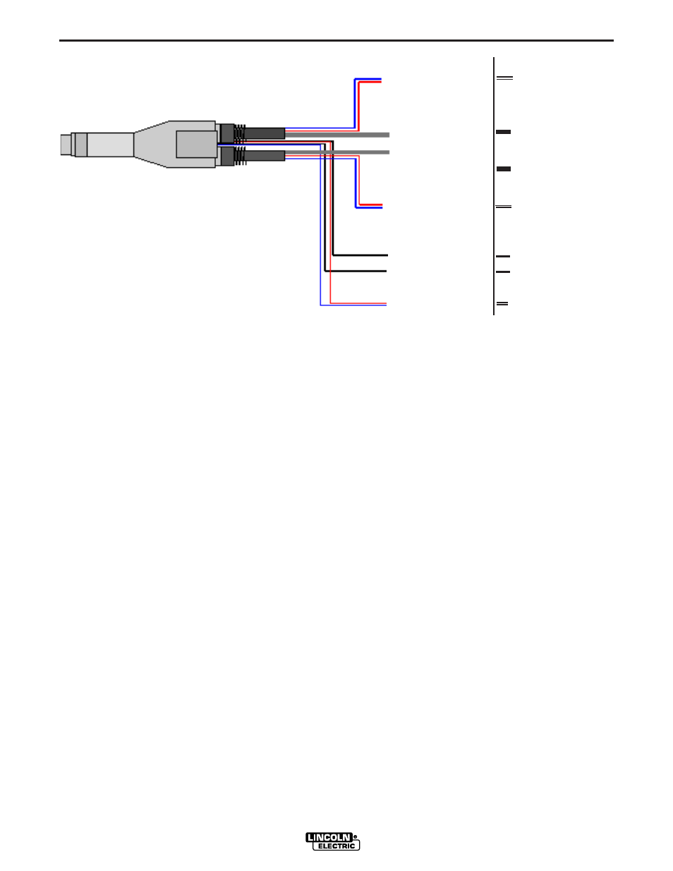
CONNECTION DIAGRAM
For G3494-2 thru -6 and G3494-2A thru -6A
FIGURE 2
To Lead Water cooler
To Lead Water cooler
To Lead Wire Feeder
To Lead Wire Feeder
and Shielding Gas
Solenoid
To Trail Wire Feeder
and Shielding Gas
Solenoid
To Trail Wire Feeder
To Trail Water cooler
To Trail Water cooler
To Shielding Gas
No Hose
To Air Blast
To Air Blast
To Nozzle Water cooler
To Nozzle Water cooler
G3494-2 thru -6
G3494-2A thru -6A