Installation, Installing the statiflex 200-m – Lincoln Electric IM625 Statiflex 200-M K1654-1 User Manual
Page 10
A-3
INSTALLATION
STATIFLEX 200-M
A-3
INSTALLING THE STATIFLEX 200-M
(continued)
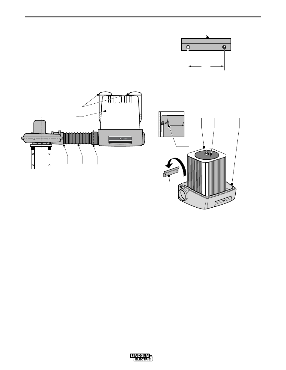
Fit the small (6” diam.) side of the 6”-8” Reducer over
the outlet of the SF2400 Fan (Fig. 1A); be sure to
slide the Reducer all the way over the rubber seal.
Secure with three sheet-metal screws through the
reducer into the plastic-molded fan outlet.
Fit one end of the 8” Connection hose (Fig. 1B) over
the larger side of the 6”-8” Reducer. Secure with one
8” hose clamp.
Mount the Statiflex mounting bracket (Fig. 2A) to the
wall where convenient with the following in mind:
• Access to the filter (for maintenance) is by lifting the
large red cover over the (internal) filter. The easiest
method is to lift the entire filter unit off the mounting
bracket (about 2-4” higher than its mounting height)
and set it down on the floor, then perform any neces-
sary maintenance.
• The 8” connection hose must reach (comfortably)
the inlet of the Statiflex 200-M; the inlet (when mount-
ed) is approximately 10 in. off the left side of the
Statiflex mounting bracket.
• The Statiflex 200-M may be mounted on either side
of the fan, as long as the connection hose reaches
from the outlet of the fan to the inlet of the Statiflex
200-M.
• Recommended mounting height of the Statiflex
mounting bracket is less than 7 ft. from the floor to the
drilled holes. It is recommended to mount the bracket
about 30-36 in. off the outlet of the fan (to the right).
Before lifting the Statiflex 200-M Filter Unit onto the
mounting bracket:
• Cut the left inlet (or right, depending on which side
of the fan it is to be mounted) open (Fig. 1 C). A hack-
saw or multi-purpose power saw may be used.
• Unscrew the thumb nut and remove the filter cover
(Fig. 1D). Cut one or both outlet openings (Fig. 1E)
open. Replace the filter cover and thumb nut.
Lift the Statiflex 200-M onto the mounting bracket;
refer to Figure 3. The installation may be made per-
manent by running (2) self-tapping screws (FIg. 3E) in
through the plastic base against the wall bracket.
A
D
B
C
E
Fig. 1
A
11.4"
(290 mm)
Fig. 2
A
D
E
C
B
Fig. 3