Break-in period, Welding process – Lincoln Electric IM672 RED-D-ARC ZR-8 User Manual
Page 19
– 18 –
Kohler Engine
-
Always
pull the choke control out
when starting the engine; cold, warm or hot. Place the
“Engine” switch in the “ON” position.
Push the “START” button and crank the engine until it
starts. Release the button as soon as the engine
starts. Do not push the “START” button while the
engine is running because this will cause damage to
the ring gear and/or starter motor. After the engine
has started, slowly return the choke control to the full
“in” position (choke open).
After running at high engine speed for 10-14 seconds,
the engine will go to low idle.
Allow the engine to warm up by letting it run at low idle
for a few minutes.
Stopping the Engine
Remove all welding and auxiliary power loads and
allow engine to run at low idle speed for a few minutes
to cool the engine.
Stop the engine by placing the “Engine” switch in the
“OFF” position.
A fuel shut off valve is not required on the ZR-8
because the fuel tank is mounted below the engine.
Break-in Period
It is normal for any engine to use a greater amount of
oil until the break-in is accomplished. Check the oil
level twice a day during the break-in period (approxi-
mately 50 running hours)).
IMPORTANT: IN ORDER TO ACCOMPLISH THIS
BREAK-IN, THE UNIT SHOULD BE
SUBJECTED TO MODERATE
LOADS, WITHIN THE RATING OF
THE MACHINE. AVOID LONG IDLE
RUNNING PERIODS. REMOVE
LOADS AND ALLOW ENGINE TO
COOL BEFORE SHUTDOWN.
The engine manufacturer’s recommendation for the
running time until the first oil change is as follows:
The oil filter is to be changed at the second oil
change. Refer to the Engine Owner’s Manual for
more information.
Welding Process
Stick (Constant Current) Welding
Connect welding cables to the "TO WORK” and
"ELECTRODE” studs. Start the engine. Set the
"Polarity” switch to the desired polarity. Set the
“RANGE” switch to a setting that is equal to or slightly
greater than the desired welding current. (The
“RANGE” dial marking indicates the maximum current
for that range). Fine adjustment of the welding current
is made by adjusting the output “CONTROL” or
remote control.
For best arc stability, use settings
5 through 10.
The ZR-8 can be used with a broad range of AC and
DC stick electrodes. See “Welding Tips 1” included
with the ZR-8 for electrodes within the rating of this
unit and recommended welding currents of each.
TIG (Constant Current) Welding
The K930-1 TIG Module installed on a ZR-8 provides
high frequency and shielding gas control for AC and
DC GTAW (TIG) welding processes. The TIG Module
allows full range output control. Afterflow time is
adjustable from 0 to 55 seconds.
When using the ZR-8 for AC TIG welding of alu-
minum, the following settings and electrodes are
recommended:
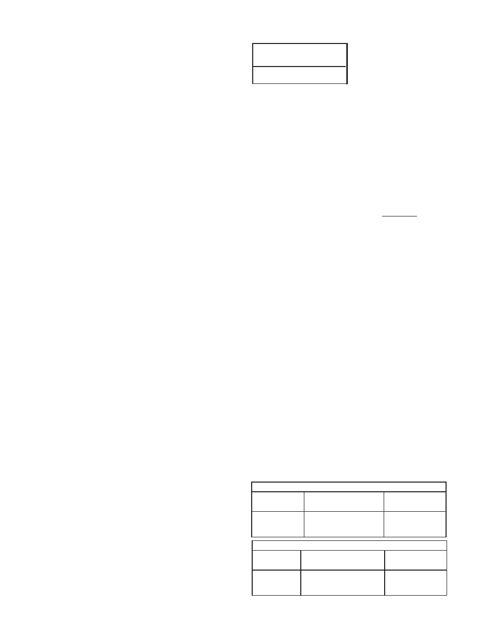
Kohler
CH20S
5 hr
SETTINGS FOR PURE TUNGSTEN
TUNGSTEN RANGE SWITCH
APPROXIMATE
DIAMETER (in.) SETTINGS CURRENT RANGE
1/8 70, 90, or 125 80 - 150 Amps
3/32 50, 70, or 90 45 - 130 Amps
1/16 50, or 70 40 - 80 Amps
SETTINGS FOR 1% THORIATED TUNGSTEN
TUNGSTEN RANGE SWITCH
APPROXIMATE
DIAMETER (in.) SETTINGS CURRENT RANGE
1/8 70, 90, 125, or 175 80 - 225 Amps
3/32 50, 70, 90, or 125 50 - 180 Amps
1/16 50, 70, or 90 45 - 120 Amps