Operation, B-4 welding process – Lincoln Electric IM752 RANGER 8 User Manual
Page 21
B-4
OPERATION
B-4
WELDING PROCESS
STICK (CONSTANT CURRENT) WELDING
Connect welding cables to the "TO WORK
”
and
"ELECTRODE
”
studs. Start the engine. Set the
"Polarity
”
switch to the desired polarity. Set the
“
RANGE
”
switch to a setting that is equal to or slightly
greater than the desired welding current. (The
“
RANGE
”
dial marking indicates the maximum current
for that range). Fine adjustment of the welding current
is made by adjusting the output
“
CONTROL
”
or
remote control. For best arc stability, use settings
5 through 10.
The Ranger 8 can be used with a broad range of AC
and DC stick electrodes. See
“
Welding Tips 1
”
included with the Ranger 8 for electrodes within the
rating of this unit and recommended welding currents
of each.
TIG (CONSTANT CURRENT) WELDING
The K930-[ ] TIG Module installed on a Ranger 8 pro-
vides high frequency and shielding gas control for AC
and DC GTAW (TIG) welding processes. The TIG
Module allows full range output control. Afterflow time
is adjustable from 0 to 55 seconds.
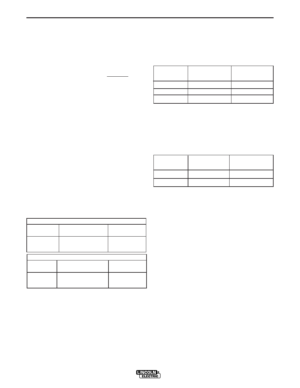
When using the Ranger 8 for AC TIG welding of
aluminum, the following settings and electrodes are
recommended:
The K930-[ ] TIG Module should be used with the
Ranger 8 on high idle to maintain satisfactory opera-
tion. It can be used in the AUTO position but the
delay going to flow idle after welding is ceased will be
increased if the AFTERFLOW CONTROL is set above
10 seconds.
WIRE FEED WELDING PROCESSES
(CONSTANT VOLTAGE)
The Innershield
®
electrode recommended for use with
the Ranger 8 is NR
®
-211-MP. The electrode sizes and
welding ranges that can be used with the Ranger 8
are shown in the following table:
The Ranger 8 is recommended for limited
“
MIG
”
weld-
ing (GMAW - gas metal arc welding). The recom-
mended electrodes are .030
”
and .035
”
L-50 and L-56.
They must be used with a blended shielding gas such
as C25 (75% Argon - 25% CO
2
). The welding ranges
that can be used with the Ranger 8 are shown in the
following table:
RANGER 8
SETTINGS FOR PURE TUNGSTEN
TUNGSTEN RANGE SWITCH
APPROXIMATE
DIAMETER (in.) SETTINGS CURRENT RANGE
1/8 70, 90, or 125 80 - 150 Amps
3/32 50, 70, or 90 45 - 130 Amps
1/16 50, or 70 40 - 80 Amps
SETTINGS FOR 1% THORIATED TUNGSTEN
TUNGSTEN RANGE SWITCH
APPROXIMATE
DIAMETER (in.) SETTINGS CURRENT RANGE
1/8 70, 90, 125, or 175 80 - 225 Amps
3/32 50, 70, 90, or 125 50 - 180 Amps
1/16 50, 70, or 90 45 - 120 Amps
Diameter Wire Speed Approximate
(in.) Range In./Min. Current Range
.035
80 - 110
75A to 120A
.045
70 - 130
120A to 170A
.068
40 - 90
125A to 210A
Diameter Wire Speed Approximate
(in.) Range In./Min. Current Range
.030
80 - 110
75A to 120A
.035
70 - 130
120A to 170A