Operation – Lincoln Electric IM893 RANGER 305 D (CE) User Manual
Page 25
AUXILIARY POWER:
Start the engine and set the IDLER control switch to
the desired operating mode. Full power is available
regardless of the welding control settings providing no
welding current is being drawn.
Simultaneous Welding and Auxiliary Power Loads
While welding, the amount of 3-phase Auxiliary power
available is reduced. (See table A.4)
RANGER 305D (CE)
B-6
OPERATION
B-6
When in the TOUCH START TIG mode and when a
Amptrol is connected to the 6-pin Connector the OUT-
PUT dial is used to set the maximum current range of
the CURRENT CONTROL of the Amptrol.
The ARC CONTROL is not active in the TIG mode.
The RANGER 305D (CE) can be used in a wide variety
of DC TIG welding applications. In general the ʻTouch
Startʼ feature allows contamination free starting without
the use of a Hi-frequency unit. If desired, the K930-2
TIG Module can be used with the RANGER 305D (CE).
The settings are for reference.
RANGER 305D (CE) settings when using the K930-2
TIG Module with an Amptrol or Arc Start Switch:
• Set the MODE Switch to the TOUCH START TIG
setting.
• Set the "IDLER" Switch to the "AUTO" position.
• Set the "WELDING TERMINALS" switch to the
"REMOTELY CONTROLLED" position. This will keep
the "Solid State" contactor open and provide a “cold”
electrode until the Amptrol or Arc Start Switch is
pressed
When using the TIG Module, the OUTPUT control on
the RANGER 305D (CE) is used to set the maximum
range of the CURRENT CONTROL on the TIG module
or an Amptrol if connected to the TIG Module. (See
Table B.2.)
WIRE WELDING-CV
Connect a wire feeder to the Ranger 305D (CE) accord-
ing to the instructions in INSTALLATION INSTRUC-
TIONS Section.
The RANGER 305D (CE) in the CV-WIRE mode, per-
mits it to be used with a broad range of flux cored wire
(Innershield and Outershield) electrodes and solid wires
for MIG welding (gas metal arc welding). Welding can
be finely tuned using the ARC CONTROL. Turning the
ARC CONTROL clockwise from –10 (soft) to +10 (crisp)
changes the arc from soft and washed-in to crisp and
narrow. It acts as an inductance/pinch control. The
proper setting depends on the procedure and operator
preference. Start with the dial set at 0.
For any electrodes the procedures should be kept
within the rating of the machine. For additional elec-
trode information see WWW.Lincolnelectric.com or
the appropriate Lincoln publication.
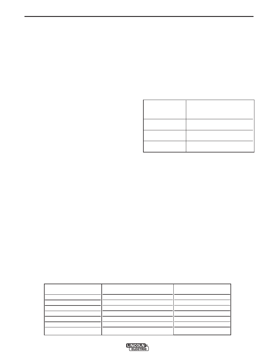
ARC GOUGING
The RANGER 305D (CE) can be used for limited arc
gouging. For optimal performance, set the MODE
switch to CC-STICK and the ARC CONTROL to +10.
Set the OUTPUT CONTROL knob to adjust output
current to the desired level for the gouging electrode
being used according to the ratings in the following
Table B.3.
Carbon Diameter
Current Range (DC, electrode
positive)
1/8"
60-90 Amps
5/32"
90-150 Amps
3/16"
200-250 Amps
TABLE B.3
WELDING OUTPUT-
AMPS
0
50
100
150
200
250
PERMISSIBLE POWER-WATTS
(UNITY POWER FACTOR)
8000
6500
5000
3500
2000
0
PERMISSIBLE AUX
POWER @400V, 3PHASE
12 Amps
9 Amps
7 Amps
5 Amps
3 Amps
0 Amps
TABLE A.4