Installation, Caution warning – Lincoln Electric IM893 RANGER 305 D (CE) User Manual
Page 17
Connections must be made by a licensed electrician
who can determine how the power can be adapted to
the particular installation and comply with all applica-
ble electrical codes.
• Take necessary steps to assure load is limited to
the capacity of the RANGER 305D (CE).
• Only a licensed, certified, trained electrician
should install the machine to a premises or resi-
dential electrical system. Be certain that:
• The installation complies with the National
Electrical Code and all other applicable electri-
cal codes.
• The premises is isolated and no feedback into
the utility system can occur. Certain laws
require the premises to be isolated before the
generator is linked to the premises. Check your
local requirements.
-----------------------------------------------------------------------
TABLE A-1
CABLE INSTALLATION
Install the welding cables to your machine as follows:
1. The diesel engine must be OFF to install welding
cables.
2. Remove the flanged nuts from the output terminals.
3. Connect the electrode holder and work cables to the
weld output terminals. The terminals are identified
on the case front.
4. Tighten the flanged nuts securely.
5. Be certain that the metal piece you are welding (the
“work”) is properly connected to the work clamp and
cable.
6. Check and tighten the connections periodically.
• Loose connections will cause the output termi-
nals to overheat. The terminals may eventually
melt.
• Do not cross the welding cables at the output ter-
minal connection. Keep the cables isolated and
separate from one another.
-----------------------------------------------------------------------
AUXILIARY POWER
The auxiliary power capacity is 8500 watts Peak, 8,000
Watts Continuous of 50 Hz, three phase power. The
auxiliary power capacity rating in watts is equivalent to
volt-amperes at unity power factor. The max permissi-
ble current of the 400 VAC output is 12 amps. Output
voltage is within ± 10% at all loads up to the rated
capacity.
STANDBY POWER CONNECTIONS
The machine is suitable for temporary, standby or
emergency power using the engine manufacturerʼs
recommended maintenance schedule.
The machine can be permanently installed as a stand-
by power unit for 400 VAC, three phase, 12 amp ser-
vice.
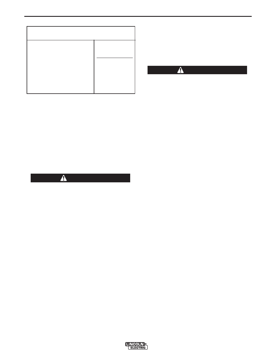
TOTAL COMBINED LENGTH OF
ELECTRODE AND WORK CABLES
Cable Length
0-30 meters (0-100Ft.)
30-46 meters (100-150 Ft.)
46-61 meters (150-200 Ft.)
Cable Size for
305 Amps
100% Duty Cycle
1 / 0 AWG
2 / 0 AWG
3 / 0 AWG
CAUTION
WARNING
A-5
INSTALLATION
RANGER 305D (CE)
A-5