Operation, Warning – Lincoln Electric IM784 PRO 100 User Manual
Page 17
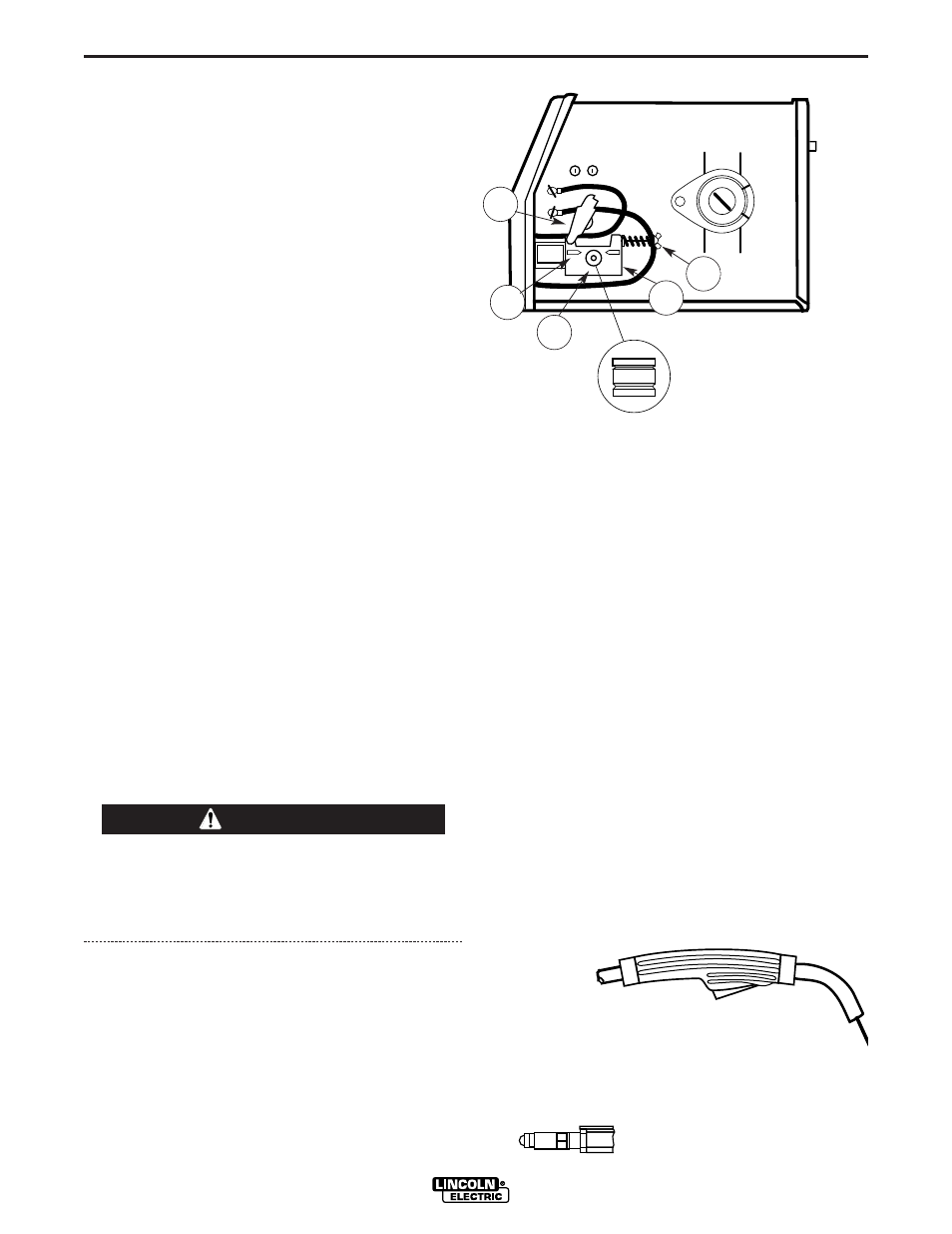
Gun Handle
Gas Diffuser/
Contact Tip
Gas Nozzle
FIGURE B.5
B-4
OPERATION
B-4
Note:
The brake should be adjusted with a spool of
wire installed. When properly adjusted it should
move freely but not coast.
Friction Brake Adjustments
1. With wire spool installed, check free movement
and coast of the spool.
2. To tighten the brake turn the wing nut clockwise in
1/4 turn increments until coasting stops.
3. To loosen the brake turn the wing nut counter-
clockwise in 1/4 turn increments until the wire
spool moves freely without coasting.
Wire Threading
Refer to Figure B-4
1. Release the Spring Loaded Pressure Arm (1)
rotate the Idle Roll Arm (2) away from. the Wire
Feed Drive Roll (3). Ensure that the groove size in
the feeding position on the drive roll matches the
wire size being used.
2. Carefully detach the end of the wire from the
spool. To prevent the spool from unwinding,
maintain tension on the wire until after step 5.
3. Cut the bent portion of wire off and straighten the
first 4
”
(100 mm).
4. Thread the wire through the In-going guide tube
(4), over the drive roll (3), and into the out-going
guide tube (5).
5. Close the idle roll arm and latch the spring loaded
pressure arm (2) in place. Rotate the spool coun-
terclockwise if required in order to take up extra
slack in the wire.
When inching the welding wire, the drive rolls, the
gun connector block and the gun contact tip are
electrically energized relative to work and ground
and remain energized for several seconds after
the gun trigger is released.
6. The idle roll pressure adjustment wing nut is nor-
mally set for mid-position on the pressure arm
threads. If feeding problems occur because the
wire is flattened excessively, turn the pressure
adjustment counter-clockwise to reduce distortion
of the wire. Slightly less pressure may be required
when using 0.023
–
0.025
”
(0,6 mm) wire. If the
drive roll slips while feeding wire, the pressure
should be increaseduntil the wire feeds properly.
7. Refer to Figure B.5. Remove gas nozzle and con-
tact tip from end of gun.
8. Turn the PRO 100 ON (
“
I
”
).
9. Straighten the gun cable assembly.
10. Depress the gun trigger switch and feed welding
wire through the gun and cable. (Point gun away
from yourself and others while feeding wire.)
Release gun trigger after wire appears at end of
gun.
11. Turn the PRO 100 OFF (
“
O
”
).
12. Replace contact tip and gas nozzle.
13. Refer to Figure B-6. Cut the wire off 3/8
” –
1/2
”
(10
–
13 mm) from the end of the tip. The PRO 100 is
now ready to weld.
PRO 100
WARNING
FIGURE B.4
The Wire Drive Feed Roll can
accommodate two wire sizes by
flipping the wire drive feed roll
over.
2
5
3
4
1